Georgio_P
Member
- Joined
- Mar 10, 2024
- Messages
- 37
- Reaction score
- 4
Back in the early 90's , before what we know as the Internet today really existed for most of us, Victor Litz used to mail out a paper sales ad.
I called in about a used Marshall 8008 Valvestate solid state amp listing for a few hundred dollars. It seemed like a fair price back then.
Salesman said that this amp would have no problem to drive my 4x12 cabinet with 75W Celestions wired in parallel to the full extent of their limits.
I paid around $20 for shipping. I was like 22 years old, short on cash, and was hoping this would fit the bill (hope is not a strategy).
When it arrived, I felt that it lacked the expected punch + gain @ 4 Ohms, hence barely powered this 300W cabinet, so I shelved it.
it never seemed to drive the 4 12's as expected, it did, but just barely...IMO..
No returns on used items, All sales final, and I was 6 states over, and they knew I was over a barrel.
Fast forward and it's 2024, I need a 2x12 combo amp, and held on to it all these years, thinking I could re-purpose this someday at a lesser capacity....
Reading some reviews from Reverb and other used gear sites, most say that the 8008 amp in general, should indeed produce more power than mine seemed to ever have.
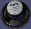
Today, I just need this 8008 to drive 2 12" 16 Ohm 100W "KICS" speakers(another story) that I have laying around ( wired in parallel).
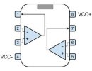
Expecting to get 8 Ohms on Channel B, only using Channel B for in / out connected to these two 12's...
Channel A to be unused.
I powered this amp up for first time in 10 years. It's been properly stored in a cool dry basement.
Red power light came on, great. It worked for two minutes with some humming (still sounded weak, but only producing 40W at 8 Ohms right?) ...then.....Pop and smoke!
Blew both channel fuses, but not the main. Channel A had no input or output.
I was running a Hotone Ampero into the channel B 1/4" input with substantial gain coming into channel B.
Now, I am waiting for new T6.3A 250V fuses to arrive, but what else should I check for in the meantime?
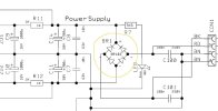
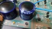
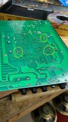
I am looking around for replacements for the two large blue bulged capacitors.
They seem to be SAMWHA CE-HC 85°C 50WV, 30mm x 30mm capacitors.
If I had to guess where they are, it would be at C11 and C14 in the PDF schematic, listed as 4700uF, and 50V.
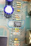
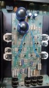
Picture here for reference. The rest of the internals look OK to the naked eye (no burnt traces or components).
I have a DVM, but am unsure of what the issue is.
Many thanks in advance,
George
I called in about a used Marshall 8008 Valvestate solid state amp listing for a few hundred dollars. It seemed like a fair price back then.
Salesman said that this amp would have no problem to drive my 4x12 cabinet with 75W Celestions wired in parallel to the full extent of their limits.
I paid around $20 for shipping. I was like 22 years old, short on cash, and was hoping this would fit the bill (hope is not a strategy).
When it arrived, I felt that it lacked the expected punch + gain @ 4 Ohms, hence barely powered this 300W cabinet, so I shelved it.
it never seemed to drive the 4 12's as expected, it did, but just barely...IMO..
No returns on used items, All sales final, and I was 6 states over, and they knew I was over a barrel.
Fast forward and it's 2024, I need a 2x12 combo amp, and held on to it all these years, thinking I could re-purpose this someday at a lesser capacity....
Reading some reviews from Reverb and other used gear sites, most say that the 8008 amp in general, should indeed produce more power than mine seemed to ever have.
Today, I just need this 8008 to drive 2 12" 16 Ohm 100W "KICS" speakers(another story) that I have laying around ( wired in parallel).
Expecting to get 8 Ohms on Channel B, only using Channel B for in / out connected to these two 12's...
Channel A to be unused.
I powered this amp up for first time in 10 years. It's been properly stored in a cool dry basement.
Red power light came on, great. It worked for two minutes with some humming (still sounded weak, but only producing 40W at 8 Ohms right?) ...then.....Pop and smoke!
Blew both channel fuses, but not the main. Channel A had no input or output.
I was running a Hotone Ampero into the channel B 1/4" input with substantial gain coming into channel B.
Now, I am waiting for new T6.3A 250V fuses to arrive, but what else should I check for in the meantime?
I am looking around for replacements for the two large blue bulged capacitors.
They seem to be SAMWHA CE-HC 85°C 50WV, 30mm x 30mm capacitors.
If I had to guess where they are, it would be at C11 and C14 in the PDF schematic, listed as 4700uF, and 50V.
Picture here for reference. The rest of the internals look OK to the naked eye (no burnt traces or components).
I have a DVM, but am unsure of what the issue is.
Many thanks in advance,
George
Attachments
Last edited:
")