-
We are looking to make improvements to the Classifieds! Help us determine what improvements we can make by filling out this classifieds survey. Your feedback is very appreciated and helpful!
Take survey
You are using an out of date browser. It may not display this or other websites correctly.
You should upgrade or use an alternative browser.
You should upgrade or use an alternative browser.
Completed JohnH Attenuators?
- Thread starter Gene Ballzz
- Start date
This site may earn a commission from merchant affiliate links like Ebay, Amazon, and others.

donwagar
Well-Known Member
I just finished my second M2 (for a friend). Just a standard 50W M2. It was way easier than the first one (I find that with pretty well everything in life).
The huge bonus for me was Gene's layout and wiring diagram, thanks man!


@stickyfinger asked for costs: this was $185 Canadian, but I didn't try to cut costs anywhere. Almost all the parts came from Mouser. The inductor came out of Quebec with IIRC a $25 freight cost. But as I didn't make this for me, I wanted best quality parts. And charged my friend for them, lol.
The huge bonus for me was Gene's layout and wiring diagram, thanks man!
@stickyfinger asked for costs: this was $185 Canadian, but I didn't try to cut costs anywhere. Almost all the parts came from Mouser. The inductor came out of Quebec with IIRC a $25 freight cost. But as I didn't make this for me, I wanted best quality parts. And charged my friend for them, lol.
Last edited:
JohnH
Well-Known Member
Barnsley Boy
Active Member
Chunky switches deffo the way to go!!! Good job fellaI just finished my second M2 (for a friend). Just a standard 50W M2. It was way easier than the first one (I find that with pretty well everything in life).
The huge bonus for me was Gene's layout and wiring diagram, thanks man!
View attachment 103823
View attachment 103824
Barnsley Boy
Active Member
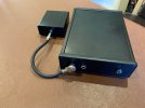
Some pics of "son of" DEFCON 1:
The extension box converts my 8 ohm M2 into a 4 ohm version by simply plugging it in parallel with the main circuit. Big thanks to @JohnH as usual for the guidance and wisdom.
The extension box converts my 8 ohm M2 into a 4 ohm version by simply plugging it in parallel with the main circuit. Big thanks to @JohnH as usual for the guidance and wisdom.
Attachments
Just finished an 100W version of the M2v. The box was formed from two 1/4" aluminum plates for the top and bottom, two 1/8" aluminum 'U' channels for the front and back, and two 1/8" aluminum 'L' pieces for the sides. Overall dimensions are 8" W x 8" D x 3.5" H. Bronze screen is behind the ventilation holes on the sides. It took a quite a bit of planning to fit all the pieces together in a buildable form. Thanks John H.


JohnH
Well-Known Member
DeluxeReverb
New Member
- Joined
- Apr 7, 2022
- Messages
- 5
- Reaction score
- 6
Just finished an M2 with a bypass switch on the back. I know that vent holes in the top are ideal, but I’ve got lots of holes on the sides and bottom, and I’m using it with 20w or less amps (Deluxe Reverb, SV20, etc.). Even after 2 hours of running the amps at 60% and at heavy attenuation, the top of the case where the components are mounted only got to body temperature. Seriously, my cat is warmer.
My bases of comparison are a Weber MiniMass and the attenuator built into my 12w Aiken Tomcat, and this M2 is the best of the lot! Lettering to come later.
Oh, and Hello all from my first post! I joined this forum based on the attenuator design thread. Thanks, @JohnH and the others who contributed to this project.
Update: My total cost for this build was right around $185USD. I went with Mouser for the enclosure and resistors, Parts Express for the inductor, and Antique Electronic Supply for the remainder of the components. I could have saved money by ordering from eBay or other sources, but I’ve had a lot of experience with the suppliers I used for this build, and I knew I’d get the parts quickly.
Oh, and I did end up wiring a connection from the enclosure to the shield of the amplifier input jack after these pics were taken. Before that, touching any non-painted part of the enclosure like the switches or exposed screws would make a super-loud oscillation noise through the speakers. Having a chassis connected in this way is pretty common for attenuators, so it’s the first thing I tried and it completely resolved the issues I was having. Using an ordinary Switchcraft-style jack at the amp input would’ve solved the noise also.
Last edited:
JohnH
Well-Known Member
hi @DeluxeReverb , that look great and thanks for posting it! I'm glad it's working out.
With the heat, it seems like the effects of temperature kick in at a very different rate than for audible volume. 20w, 50w and 100w are just a small increment of volume apart, but a big difference in how hot they feel. With most builds, 20w just gets warm, 50w gets hot and 100w gets smokin' without some serious cooling features!
With the heat, it seems like the effects of temperature kick in at a very different rate than for audible volume. 20w, 50w and 100w are just a small increment of volume apart, but a big difference in how hot they feel. With most builds, 20w just gets warm, 50w gets hot and 100w gets smokin' without some serious cooling features!
stickyfinger
Well-Known Member
- Joined
- Nov 11, 2010
- Messages
- 1,170
- Reaction score
- 699
Can you fellas edit your posts with a estimate total cost of your project?
Gene Ballzz
Well-Known Member
Just finished an M2 with a bypass switch on the back. I know that vent holes in the top are ideal, but I’ve got lots of holes on the sides and bottom, and I’m using it with 20w or less amps (Deluxe Reverb, SV20, etc.). Even after 2 hours of running the amps at 60% and at heavy attenuation, the top of the case where the components are mounted only got to body temperature. Seriously, my cat is warmer.
My bases of comparison are a Weber MiniMass and the attenuator built into my 12w Aiken Tomcat, and this M2 is the best of the lot! Lettering to come later.
Oh, and Hello all from my first post! I joined this forum based on the attenuator design thread. Thanks, @JohnH and the others who contributed to this project. View attachment 106726View attachment 106727
View attachment 106724View attachment 106725
Very nice and neat execution! I love the coutersunk, recessed screws! Elegantly simple!
Can you fellas edit your posts with a estimate total cost of your project?
The prices for components vary so widely and wildly from source to source and choice to choice that the best estimate for a bare bones, 50 watt M2, no extra bells or whistles ranges from $75 to $150.
Dat's Da Facts!
Gene
DeluxeReverb
New Member
- Joined
- Apr 7, 2022
- Messages
- 5
- Reaction score
- 6
Done, with extra commentary.Can you fellas edit your posts with a estimate total cost of your project?


Another M2 build.
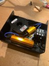
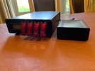
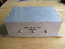
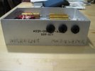
The case is a nice heavy aluminium box that housed aircraft electronics. I am going to use it with my 1987 JMP 50W (circa 1973), 18W clone, 5E3 clone, and a future 5881 homebuilt amp. Cosmetically, I am going to leave it as is.
Cost:
Resistors and heat sink pads cost about 90CDN shipped from Digikey.ca
Cliff jacks about 10CDN from Nextgenguitars.ca
Inductor about 13Cdn from Solen.ca. Shipping was around 10
Aluminum case cost 20Cdn
Misc hardware and wire from the scrap bin
So around 150Cdn or 115USD for the build.
A big hats off to John H for all of his outstanding work on this project, and for freely sharing it with the rest of us.
Steve
Attachments
Last edited:
JohnH
Well-Known Member
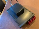
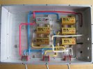
There is only one box which has two separate internal compartments. It is a solid piece of cast aluminium with a divider shelf half way up. I suspect it was made this way to isolate different parts of the rf modulator circuitry that it contained.Hi @Chappy , thanks for posting . That looks to be a very neat build. I'm seeing two box sections with sides, one with stage 1 and the jacks, the other with switches and the rest? is there a photo of it all together?
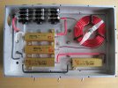
So my build has half of the circuitry stacked on top of the other on either side of that divider shelf. The images are a look inside the same box from the bottom, and then the top. The wires attaching all of it together run through existing holes in the divider shelf.
Thanks again for sharing your excellent project. I was going to sell my JMP 50 head, but with this device, I may decide to keep it
")
Cheers
Steve
JohnH
Well-Known Member
Ah now I understand! Thanks, and it looks great. Have you tried it yet? (after resistance tests to be sure)
Yes, and it seems to be working properly. I have only used it a bit so far. I am going to check all of my connections one more time to make sure I didn't make an error or a poor solder joint. I'm contemplating attaching a large heat sink on the top as well. It got really warm after playing the JMP50 through it for 10 min or so. Barely got warm with my 15W 6V6 homebrew head.Ah now I understand! Thanks, and it looks great. Have you tried it yet? (after resistance tests to be sure)
Steve
Gene Ballzz
Well-Known Member
Yes, and it seems to be working properly. I have only used it a bit so far. I am going to check all of my connections one more time to make sure I didn't make an error or a poor solder joint. I'm contemplating attaching a large heat sink on the top as well. It got really warm after playing the JMP50 through it for 10 min or so. Barely got warm with my 15W 6V6 homebrew head.
Steve
Additionally, some holes for ventillation wouldn't hurt. If you crank that 50 watter through for a while, it'll likely be mostly toastly within 30 minutes! Nice looking build!
Just Toastin'
Gene