• We are looking to make improvements to the Classifieds! Help us determine what improvements we can make by filling out this classifieds survey. Your feedback is very appreciated and helpful!

    Take survey

Completed JohnH Attenuators?

  • Thread starter Gene Ballzz
  • Start date
  • This site may earn a commission from merchant affiliate links like Ebay, Amazon, and others.

BillJ

New Member
Joined
Jun 18, 2023
Messages
7
Reaction score
2
It's really good to see these attenuators that people have made, I would like to try one myself. I've seen that there is a thread about building them, but it's 175 pages!

I've seen a parts list for version M of the JohnH attenuator on page 13, but rather than reading the rest of the 175 pages could someone please guide me to the right page. I want to build a 16 Ohm one for a 30W Valvetone amp, which is Australian, and the M model @JohnH describes sounds good.
 

JohnH

Well-Known Member
Joined
May 31, 2008
Messages
6,155
Reaction score
5,062
Location
Wilton NSW
Hi @BillJ The first post of the main thread has all you need, with links to a few other key posts. M2 is the latest basic version, and the 50w build as specced there would be fine .
 

BillJ

New Member
Joined
Jun 18, 2023
Messages
7
Reaction score
2
Hi @BillJ The first post of the main thread has all you need, with links to a few other key posts. M2 is the latest basic version, and the 50w build as specced there would be fine .
I must've first looked at the main thread longer ago than i thought, as all that extra stuff wasn't there. I wanted to build one then, but I thought it's probably a stretch for me, and I think it still is.

Since then I've bought 2 Audiostorm Hot boxes, and I really like how they sound, but the first one attenuates a minimum of -10dB, and it's great for home use, but too much for playing out. So I bought another one with a minimum of -6dB, but that's still too much. Around -3.5dB would probably be ideal.

But it looks like the inductance coil isn't used unless you are at -7dB, and that's too much. Anyway, thanks for your help, I think this might be beyond me.
 

JohnH

Well-Known Member
Joined
May 31, 2008
Messages
6,155
Reaction score
5,062
Location
Wilton NSW
hi @BillJ

The latest designs can have the front stage switched between -3.5 and -7 dB , fully reactive including the coil. If that's all that's needed, the rest can be omitted. On the main attenuator thread @Dretot is just about to test his build of exactly that...
 

BillJ

New Member
Joined
Jun 18, 2023
Messages
7
Reaction score
2
hi @BillJ

The latest designs can have the front stage switched between -3.5 and -7 dB , fully reactive including the coil. If that's all that's needed, the rest can be omitted. On the main attenuator thread @Dretot is just about to test his build of exactly that...
Thanks again @JohnH. I saw the drawing you did for @Dretot, that's really good, I think even I can do that. I'll start looking for the parts and get going on it.
 

Dretot

New Member
Joined
Feb 9, 2022
Messages
19
Reaction score
13
Thanks again @JohnH. I saw the drawing you did for @Dretot, that's really good, I think even I can do that. I'll start looking for the parts and get going on it.
Go for it! I built mine with average skills. I've never put together anything like this before. Took my time, step by step and bam... it's a beautiful thing. I'm loving mine, can't stop playing :)
 

BillJ

New Member
Joined
Jun 18, 2023
Messages
7
Reaction score
2
Go for it! I built mine with average skills. I've never put together anything like this before. Took my time, step by step and bam... it's a beautiful thing. I'm loving mine, can't stop playing :)
Thanks for the encouragement.
 

parsnip

New Member
Joined
Jun 16, 2023
Messages
9
Reaction score
11
Hi All,

Just "finished" the enclosure for my 4ohm 50w M2. "Finished" in quotes because the letter punch method I chose didn't turn out as well as I had hoped. See below. I was not drunk. Or even tired.

I found this thread and the other 178p+ thread very very helpful. I thought I'd write this up in a way that I would have found useful for me. I hope it is not tedious.

- Sourcing Parts: Everything came from digikey or parts express. I leaned on the parts list @Teledan posted on p6 of this thread. Only difference was I opted for stranded 18 awg wire (necessary for the way I mounted jacks and toggles), a different enclosure, and different resistor and coil values for 4ohm. Total cost was around $120.
- Layout: I leaned very heavily on the @Gene Ballzz layout on p 111 of the other thread w/ a few tweaks. Good place to start.
- Upside/Down? I opted to mount resistors and coil on the "base" of the enclosure, w/ jacks and toggles on the main part of the enclosure. I didn't like the inverted keystone shape otherwise, and it made soldering easier, especially in a small enclosure like mine.
- Enclosure: I used the hammond 1550E. One could only go smaller if you removed a phase of attenuation.
- Toggles: the minis are a pia and I definitely needed to have solid copper jumpers across them just to have the real estate for soldering.
- Bolts and nuts: the ones on @Teledan list worked perfectly w/ a 1/8" drill bit and a countersink.
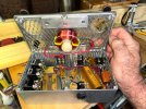
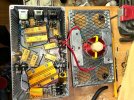
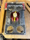
- Mounting the coil: I really liked the way this turned out. First I used a hole drill bit to cut a circle of dual wall polycarbonate (you could use other plastic, I just had this from a greenhouse job, and it is perfect). I zip tied the coil to it. Then I used a stainless bolt, nuts and washers, (tested w/ a magnet to ensure they were not magnetic). The bolt went through the base of the enclosure, and a nut secured it there. Then I used another two nuts and washers to sandwich the plastic, in order to mount the coil suspended in the space above the resistors. It keeps it isolated, and uses the real estate well.
- Cooling: I only have holes in the bottom. It hardly gets warm w/ my silvertone 1482 which is 15w. I'm going to keep an eye on it. If I think it needs it, I may add more. Or if I start using it more w/ my 60w 410 Blues Deville.
- Tricks that worked: I put all the mini bolts in, then masking taped them down to mount resistors. This made mounting resistors easy. Put one on, start the nuts, then peel back the tape in that spot, and use a screw driver and needle nose to finish the job. Also, for setting up drilling: it helped to masking tape up anyplace where holes are needed, measure twice, mark, then pre-punch all the hole locations.

Things that were challenging or I'd do differently:
- Toggles:
If I were using a larger enclosure, I'd definitely use larger toggles.
- Drilling: Drilling the 1/8" holes w/ a punch and hand held drill was easy. For the cooling holes, the bit seemed to slip a bit, and got a little sloppy. A drill press and clamp would have been better, and if I add more holes on side/top, I'll use one.
- Multiple wires meeting 1 resistor end: at times this got crowded/sloppy, and I needed to change approach to wiring. Worth thinking through before you fire up the soldering iron.
- Labelling: I wanted a very analog labeling method, and the letter punches and paint fit the bill. However, you really need a very flat, solid piece of steel to support the back side, exactly opposite where you are punching. That support needs to go to a work surface, and ideally the enclosure is clamped to it. This was hard to improv w/ the shape of the inside of the hammond box, and the regular vice/anvil I have. I'd either not do this method, or source a piece of steel that can serve this purpose better.
- Attenuation level: This is really a reach, as the thing rocks, and is great, but if I were to make an improvement for a 15W amp, I think it would be a little more useful to have the default attenuation level at -3.5 dB rather than 7. Having the attenuator fully engaged (at -31.5 dB) isn't really useful to me (it is too quiet and almost sorta silly). But it might benefit from an option a little closer to full power. I imagine this is a swap of the values of the first three resistors and the possibly coil. Calculating those values is beyond me, but maybe @JohnH will have insight into it.

Overall Performance:
This thing is so freakin cool. I have both channels of my amp jumpered w an ABY box, and both channels turned up all the way. I can go from clean to saturated power tube overdrive based entirely on my guitar's volume knob and whether I have both channels engaged. And the quality of the overdriven power tubes is just right. It is the sound I've always wanted. But without the earbleed, neighbor relations, discontent cats and loves ones, etc. I detect no degradation in tone though I do feel the difference w/ less volume (air moving, mojo, how we perceive loud vs quiet, etc.). And I can accompany friends playing acoustic this way, and it is just right. This was fun to build and totally worth it.

My only concern is if I'm going to burn through power tubes at a crazy rate.

Thanks John, Gene and all the others. What a sonic gift to humanity!


IMG_6833.jpgIMG_6834.jpgIMG_6835.jpgIMG_6837.jpgIMG_6851.jpgIMG_6852.jpgIMG_6853.jpg
 

JohnH

Well-Known Member
Joined
May 31, 2008
Messages
6,155
Reaction score
5,062
Location
Wilton NSW
Hi @parsnip

Congrats on getting that together and I'm glad it works well. I actually like the way the punched writing looks, like a well-used Underwood typewriter! Thanks for the full write-up that will help others.

That case size is the same as I used for my prototype, and yes whichever way you lay out the parts it's a squeeze! Next time I'll go bigger.

On cooling, probably with a 15W amp the need for vents at all is moot.

Getting the -3.5dB option is covered by design M4, in the form of a switch to set Stage 1 to be either -3.5dB or -7dB. This feature can be used without other added M4 features. But it works properly only for getting that -3.5dB setting. Using it as a -3.5dB default for Stage 1 with other stages on messes with the numbers. with the right ratings, it's safe to do this but at -3.5dB the amp sees a lot of reactance from the speaker as well as the coil, then adding more stages it's mostly the coil. It's too much of a range to get properly right at all settings. With Stage 1 at -7dB there's enough seperation that it's all much more consistent. So with M4 I designed it with this in mind, but its still ok to try all switch settings.

(post omments for parsnips build here, further general discussion please revert to the main thread)
 

dbishopbliss

New Member
Joined
May 24, 2021
Messages
26
Reaction score
11
Hi All,

Just "finished" the enclosure for my 4ohm 50w M2. "Finished" in quotes because the letter punch method I chose didn't turn out as well as I had hoped. See below. I was not drunk. Or even tired.

I found this thread and the other 178p+ thread very very helpful. I thought I'd write this up in a way that I would have found useful for me. I hope it is not tedious.

- Sourcing Parts: Everything came from digikey or parts express. I leaned on the parts list @Teledan posted on p6 of this thread. Only difference was I opted for stranded 18 awg wire (necessary for the way I mounted jacks and toggles), a different enclosure, and different resistor and coil values for 4ohm. Total cost was around $120.
- Layout: I leaned very heavily on the @Gene Ballzz layout on p 111 of the other thread w/ a few tweaks. Good place to start.
- Upside/Down? I opted to mount resistors and coil on the "base" of the enclosure, w/ jacks and toggles on the main part of the enclosure. I didn't like the inverted keystone shape otherwise, and it made soldering easier, especially in a small enclosure like mine.
- Enclosure: I used the hammond 1550E. One could only go smaller if you removed a phase of attenuation.
- Toggles: the minis are a pia and I definitely needed to have solid copper jumpers across them just to have the real estate for soldering.
- Bolts and nuts: the ones on @Teledan list worked perfectly w/ a 1/8" drill bit and a countersink.
- Mounting the coil: I really liked the way this turned out. First I used a hole drill bit to cut a circle of dual wall polycarbonate (you could use other plastic, I just had this from a greenhouse job, and it is perfect). I zip tied the coil to it. Then I used a stainless bolt, nuts and washers, (tested w/ a magnet to ensure they were not magnetic). The bolt went through the base of the enclosure, and a nut secured it there. Then I used another two nuts and washers to sandwich the plastic, in order to mount the coil suspended in the space above the resistors. It keeps it isolated, and uses the real estate well.
- Cooling: I only have holes in the bottom. It hardly gets warm w/ my silvertone 1482 which is 15w. I'm going to keep an eye on it. If I think it needs it, I may add more. Or if I start using it more w/ my 60w 410 Blues Deville.
- Tricks that worked: I put all the mini bolts in, then masking taped them down to mount resistors. This made mounting resistors easy. Put one on, start the nuts, then peel back the tape in that spot, and use a screw driver and needle nose to finish the job. Also, for setting up drilling: it helped to masking tape up anyplace where holes are needed, measure twice, mark, then pre-punch all the hole locations.

Things that were challenging or I'd do differently:
- Toggles:
If I were using a larger enclosure, I'd definitely use larger toggles.
- Drilling: Drilling the 1/8" holes w/ a punch and hand held drill was easy. For the cooling holes, the bit seemed to slip a bit, and got a little sloppy. A drill press and clamp would have been better, and if I add more holes on side/top, I'll use one.
- Multiple wires meeting 1 resistor end: at times this got crowded/sloppy, and I needed to change approach to wiring. Worth thinking through before you fire up the soldering iron.
- Labelling: I wanted a very analog labeling method, and the letter punches and paint fit the bill. However, you really need a very flat, solid piece of steel to support the back side, exactly opposite where you are punching. That support needs to go to a work surface, and ideally the enclosure is clamped to it. This was hard to improv w/ the shape of the inside of the hammond box, and the regular vice/anvil I have. I'd either not do this method, or source a piece of steel that can serve this purpose better.
- Attenuation level: This is really a reach, as the thing rocks, and is great, but if I were to make an improvement for a 15W amp, I think it would be a little more useful to have the default attenuation level at -3.5 dB rather than 7. Having the attenuator fully engaged (at -31.5 dB) isn't really useful to me (it is too quiet and almost sorta silly). But it might benefit from an option a little closer to full power. I imagine this is a swap of the values of the first three resistors and the possibly coil. Calculating those values is beyond me, but maybe @JohnH will have insight into it.

Overall Performance:
This thing is so freakin cool. I have both channels of my amp jumpered w an ABY box, and both channels turned up all the way. I can go from clean to saturated power tube overdrive based entirely on my guitar's volume knob and whether I have both channels engaged. And the quality of the overdriven power tubes is just right. It is the sound I've always wanted. But without the earbleed, neighbor relations, discontent cats and loves ones, etc. I detect no degradation in tone though I do feel the difference w/ less volume (air moving, mojo, how we perceive loud vs quiet, etc.). And I can accompany friends playing acoustic this way, and it is just right. This was fun to build and totally worth it.

My only concern is if I'm going to burn through power tubes at a crazy rate.

Thanks John, Gene and all the others. What a sonic gift to humanity!


View attachment 132805View attachment 132806View attachment 132807View attachment 132808View attachment 132809View attachment 132810View attachment 132811
Silvertone 1482!!!

Love mine, but it's hardly original. The filament secondary stopped working so I had to add a new transformer to the chassis. While I was in there, made a few other changes to tighten things up. Did you add a jack for the speaker or are those wires hard-wired to transformer and speaker?
 

parsnip

New Member
Joined
Jun 16, 2023
Messages
9
Reaction score
11
Hey! Sorry for the delay. I don't get notifications on this forum for some reason.

@dbishopbliss I added an output jack for both the 4ohm and 8ohm taps. I attached them to a little piece of polished angle iron on the back of the amp, which works fine for now. And I wired the speaker to a 1/4" pancake plug. This way if I want, I can unplug the combo speaker, and use a the 410 8 ohm speaker setup from my fender blues deville, which actually sounds stupendous. Less old floppy mojo, and not as good driven hard (like led zep 2 sound) but great for cleans and slight breakup.

And @JohnH I see the M4 moves you made for a 3.5 db cut in stage 1. That is perfect.

For several reasons, I am thinking of building an alternative cab for the 1482 out of pine, deeper, putting in a new inefficient alnico 12" speaker, and better baffle. I feel sketchy bringing this amp out and about as it is in really good shape and very original, but feels delicate w/ the particle board and the tolex, etc. W/ a separate enclosure, I could ride it hard, and have a better sounding and more sturdy combo for taking out and about, but still retain the option, w/ turning a few screws, to revert to the minty version. If I do this, I'm thinking, w/ the extra cab depth of building the attenuator w a bypass and the 3.5 dB cut into the cab, likely putting the resistors on the back cover mounted on a hunk of raised aluminum plate. Thinking I might aim to put the dB cut switches on front, just to make using them easier, but haven't quite figured where yet. I will not be drilling into the chassis. A project on the horizon...
 

lojo16

New Member
Joined
Aug 9, 2021
Messages
3
Reaction score
5
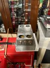
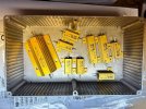
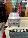
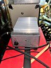
Here's my contribution, JohnH M2 8 OHM attenuator #1. It's fully functional and an "Awesome" addition to my music room. Will still be adding cosmetic and permanent markings soon. I've only used it with my Ceriatone Plexi "1986" 50w clone so far, and very happy with its performance. I'll stay in touch with experimentation of my other amps as I go, if time allows. Thanks again @JohnH & @Gene Ballzz for everything.
 

Attachments

  • 37 thumbnail.jpeg
    37 thumbnail.jpeg
    178.5 KB · Views: 111
  • 36 thumbnail.jpeg
    36 thumbnail.jpeg
    222.3 KB · Views: 110
  • 22 thumbnail.jpeg
    22 thumbnail.jpeg
    133.3 KB · Views: 101
  • 19 thumbnail.jpeg
    19 thumbnail.jpeg
    188.1 KB · Views: 92
  • 12 thumbnail.jpeg
    12 thumbnail.jpeg
    149.9 KB · Views: 88
  • 1 Arrangement To Miss ALL Unflat Contact.jpeg
    1 Arrangement To Miss ALL Unflat Contact.jpeg
    177.3 KB · Views: 93
  • thumbnail-1.jpeg
    thumbnail-1.jpeg
    147.5 KB · Views: 92
  • thumbnail-2.jpeg
    thumbnail-2.jpeg
    131.8 KB · Views: 83
  • thumbnail-3.jpeg
    thumbnail-3.jpeg
    140.2 KB · Views: 78
  • thumbnail-4.jpeg
    thumbnail-4.jpeg
    141.3 KB · Views: 106

fitz

Well-Known Yinzer
Gold Supporting Member
Joined
Apr 7, 2020
Messages
10,980
Reaction score
32,160
Location
SW PA USA
Short of a head shell style box to put this in, I'm calling my John H done.
Built from a parts kit supplied by "the Guy". :yesway:
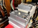
Installed everything in a 17x8x3 amp chassis enclosure on a raised 1/4" aluminum plate.
jh07.jpgjh08.jpgjh09.jpgjh10.jpgjh11.jpg
Sincerest thanks to @JohnH , @Gene Ballzz , and everyone else who has forged the path ahead of me for coming up with this cool design and for working out all the little details to make this a simple, fun to build, and very useful project.
 

Gene Ballzz

Well-Known Member
Joined
Feb 19, 2013
Messages
4,697
Reaction score
6,521
Location
Las Vegas, NV
@fitz
Very nice indeed! I notice that you've left out the foam filter on the fan, good idea! If you continue to use it for evactuation, that is the best, as that foam impedes the air flow by more than 30%. If you experience heating issues, you may want to turn that fan around and put that filter back in, but as it is, I dont expect any problems!
Nice Job, Looks Fantastic!
Gene
 

fitz

Well-Known Yinzer
Gold Supporting Member
Joined
Apr 7, 2020
Messages
10,980
Reaction score
32,160
Location
SW PA USA
OK, I found a shell for my chassis sized John H.
Picked up a Valvestate combo to get a matching cab for an AVT112.
With the amp chassis out, there plenty of room to mount my attenuator in the top of the combo.
jh12.jpg
Made a plastic plate to mount the attenuator to.
jh13.jpgjh14.jpg
The Valvestate amp has an angled control face, so the attenuator goes in on a slant.
jh15.jpg
Some screws through the corners of the new mounting plate hold it in place to the back of the face frame.
And some white on black labels.
jh16.jpg
Integrated attenuator in a stack of AVT 112 cabs for my 4210. :yesway:
jh17.jpg
 

fitz

Well-Known Yinzer
Gold Supporting Member
Joined
Apr 7, 2020
Messages
10,980
Reaction score
32,160
Location
SW PA USA
Ok, changed my mind... :shrug:
Made a short Marshall-ish shell for my John H.
Chopped up a homemade head shell I wasn't going to use again, and glued the parts back together.
(didn't take any build pics)
Salvaged all the hardware, so all just stuff from the junk pile.
Even did the tolex from 2 scraps of left overs.
jh18.jpg
Velcroed a Palmer Cab Merger to the side so I can Series two 8 ohm cabs to the 16 ohm attenuator.
jh19.jpg
Made it the same width as the 4210 head conversion shell.
jh20.jpg
 

Latest posts


Top