You are using an out of date browser. It may not display this or other websites correctly.
You should upgrade or use an alternative browser.
You should upgrade or use an alternative browser.
Does this sound right? Biasing for the first time.
- Thread starter AlexPerry
- Start date
This site may earn a commission from merchant affiliate links like Ebay, Amazon, and others.
mickeydg5
Well-Known Member
- Joined
- Sep 30, 2011
- Messages
- 28,591
- Reaction score
- 16,367
It is a weird value. Can you measure the resistance on it?It is grey (or maybe more brown, don't know what to call that color exactly), black, white, gold
There is no red there
I am curious to how your wall voltage or mains is set up over there. Do you have a 220V LINE, and a Common or Neutral plus an Earth or Ground? Or do you have two phases of 110V coming in?
mickeydg5
Well-Known Member
- Joined
- Sep 30, 2011
- Messages
- 28,591
- Reaction score
- 16,367
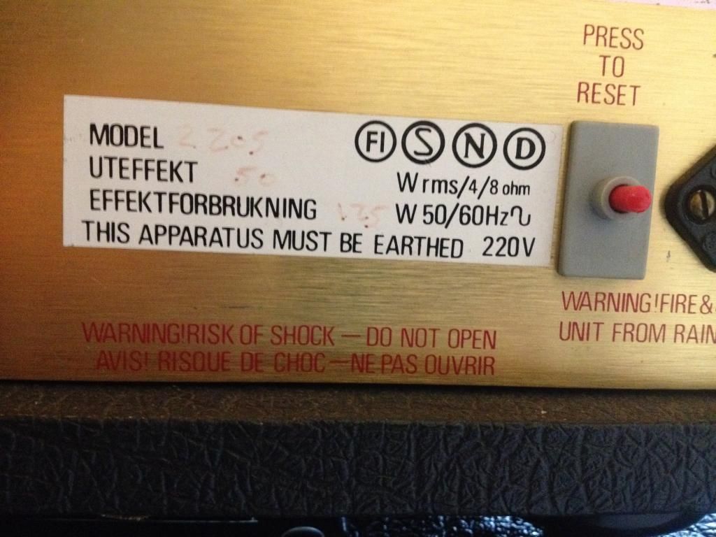
It appears to be setup for 220VAC already then. This makes since due to the fact that you have 466VDC on the plates, a good number.My wall outlet reads 223/224 V
Is it common that the bias pot gets maxed out so you can't get the bias in the recommended range? What can be done about it?
Here is a picture of the 220V on the 2205
That means that the bias supply needs attention.
Figure out that R51 position resistor.
We need the negative DC voltages at the power tube sockets pin #5 where the small resistors, 5.6k, are attached. (5.6k = green/blue/red)
I was just looking at the picture of your EL34/6550 switch. Very odd, as I see no other resistor on the switch. It looks as if the switch is just basically putting a jumper across R51. That seems to me as if that would make the negative bias voltage drop EXTREMELY low (which would give you a very hot bias option). Did you figure out if that switch is in the position shorting R51? Or is the switch in the OFF position? If you measure resistance across R51 while trying that switch (AMP powered OFF), that will tell you what it's doing.
The switch is not a bad idea, but adding another resistor with it is the way to go.
EDIT: With your amp running a cold bias, that switch has to more than likely be set at the "6550" position.
Also, give us the readings Mickey asked for in His last post. And do that test in both the EL34 and 6550 positions on that switch. You only need the AMP IN standby to do that test. That will shut off the high voltage or plate voltage on the EL34's.
EDIT:
With the multimeter on "200k Ohm" I got a reading on 100.3 or 59.8 depending on which way I hold the pins from the multimeter on the resistor (Com on left or right side) on R51
That is with the toggle switch on 6550
With the swith on EL34 I got these readings (Don't know which one is the right one)
56.4 and 43.2
How do I measure negative DC on pin 5?
With the multimeter on "200k Ohm" I got a reading on 100.3 or 59.8 depending on which way I hold the pins from the multimeter on the resistor (Com on left or right side) on the R51
How do I measure negative DC on pin 5?
I am thinking you are seeing 59K there. Repeat that ohms test AMP OFF with that switch in the opposite position. It should be the same with those red black leads either way. Make sure you have a good connection.
I am thinking you are seeing 59K there. Repeat that ohms test AMP OFF with that switch in the opposite position. It should be the same with those red black leads either way. Make sure you have a good connection.
Check th post above, I just edited it when you posted
")
But I am getting different readings when I switch the red and black leads on each side of the resistor
Check th post above, I just edited it when you posted
But I am getting different readings when I switch the red and black leads on each side of the resistor
That could be caused by residual voltage on the circuit causing odd readings with your meter. The amp is powered OFF completely?
Do that same test with that EL34/6550 switch in both positions.
EDIT: Just seen YOUR EDIT LOL.
And I'm not really sure how to measure that pin 5 thing, but the number I got touching pin 5 and that 5.6k resistor (and multimeter set om 2000mDCV was 16. (With the amp an standby)
The reading is the same wether I have the switch on 6550 or EL34
Don't know if I did it right?
The reading is the same wether I have the switch on 6550 or EL34
Don't know if I did it right?
Yes, it is off, not even connected to the outlet.
I did measure with both positions:
"With the multimeter on "200k Ohm" I got a reading on 100.3 or 59.8 depending on which way I hold the pins from the multimeter on the resistor (Com on left or right side) on R51
That is with the toggle switch on 6550
With the swith on EL34 I got these readings (Don't know which one is the right one)
56.4 and 43.2"
OK. Very strange, as I was expecting to see 0 ohms with that switch in one of the two positions. So that means that there is another resistor that the switch is adding to R51 as I suspected in the beginning. Is there another resistor on the bottom of the PCB? Or do you still have the PCB mounted to the chassis?
I am also wondering if there is a hidden resistor inside that thick black insulated wire? Can you measure resistance (AMP OFF) on each end of that black wire with the switch in each position?
It sounds to me that R51 is aprox. 43K in one position and 59K in the other. So you need to give us those pin 5 voltage readings.
mickeydg5
Well-Known Member
- Joined
- Sep 30, 2011
- Messages
- 28,591
- Reaction score
- 16,367
Make sure the amplifier is totally OFF when measuring the resistances.
When you mentioned 100.3 and 59.8 it was meant plain ohms and not k-ohms as is 100.3k?
I believe there is a resistor inside that black tube.
When you mentioned 100.3 and 59.8 it was meant plain ohms and not k-ohms as is 100.3k?
I believe there is a resistor inside that black tube.
mickeydg5
Well-Known Member
- Joined
- Sep 30, 2011
- Messages
- 28,591
- Reaction score
- 16,367
Hold on, 2000mV is far to low.And I'm not really sure how to measure that pin 5 thing, but the number I got touching pin 5 and that 5.6k resistor (and multimeter set om 2000mDCV was 16. (With the amp an standby)
The reading is the same wether I have the switch on 6550 or EL34
Don't know if I did it right?
The voltage there is in the negative 30 to 60 volt area. you need a range of VDC 100V, 200V or higher; measuring from chassis ground to the pins #5.
When measuring this the amplifier needs to be ON, operational.
With the amp in STANDBY ONLY, set your meter to read at least 100VDC. You will probe pin 5 of the EL34 socket OR you can touch those two resistors on the PCB that are feeding the ORANGE and GREEN wires that go to pins 5 (probe the sides of those two resistors next to the OR GR wires). You probe those with the red positive lead. Your black lead goes to chassis ground. Measure with switch in both positions.
Then, do the same voltage tests on both sides of that R54.
EDIT: @Mickey two minutes apart LOL
Then, do the same voltage tests on both sides of that R54.
EDIT: @Mickey two minutes apart LOL
I tried to measure with the amp AND standby ON.
I got this reading
-50.7

So your bias voltage circuit only comes on when the amp is in PLAY mode?
-50VDC is a very cold bias setting. Is that the coldest setting on the trim pot? What about the readings with the bias trim pot at both ends of its range? And what about with the switch in the opposite position with the amp ON/ON or play mode? Just turn it on only long enough to get a voltage reading then turn it off.
EDIT: This is odd that you do not have the bias voltage in standby. You might need to pull the EL34's from the amp so we can troubleshoot this a bit more safely.
Mickey will have to take over for a bit as I am getting ready to go do my own troubleshooting on my house electric panel LOL. Will be away for awhile . . . .
mickeydg5
Well-Known Member
- Joined
- Sep 30, 2011
- Messages
- 28,591
- Reaction score
- 16,367
Ricky
In post #39 I eluded to the fact that it is setup like a 3203 or JCM900.
The amplifier must be operating to get any control grid voltage in this amplifier.
In post #39 I eluded to the fact that it is setup like a 3203 or JCM900.
The amplifier must be operating to get any control grid voltage in this amplifier.
Similar threads
- Replies
- 32
- Views
- 788
- Replies
- 13
- Views
- 355
Latest posts
-
-
-

-
contour and bass not working on boost channel Marshall valvestate 4080
- Latest: david_clough
-
