JCM800 2210 Splitch PCB/Component layout diagram

  • Thread starter bordonbert
  • Start date
  • This site may earn a commission from merchant affiliate links like Ebay, Amazon, and others.

bordonbert

Member
Joined
Jan 24, 2015
Messages
59
Reaction score
15
Hi guys. I am in the middle of modding my 2210 to do a couple of things.

I'm removing the revolting IC CA3046 transistor array that Marshall had to use to do the channel switching. Honestly, BJTs are the last thing that we should be using to ground out AC signals. I have a tiny 3V relay board design with MOSFET control which will do the job properly and it sits in the original IC holes. I have now socketed the IC slot so it can take either the original CA3046 chip for a future owner who may prefer to have it as original action or my own PCB which sits on a couple of 7 pin SIL connectors tight in the socket. It only needs a couple of other simple mods on the amp PCB, remove one leg of a diode and short out a few components with wire links. All of these are easily reversible which is something I try to keep to.

I am also converting the red Drive channel LED indicator to a green/red type which just looks so much nicer I think. No, it isn't necessary but it's an easy job and it neatly fits in with the channel selector mod as the LED transistor is controlled from the same source. It only needs adding a resistor and diode to the amp PCB on existing components and swapping out the BC184 for a general purpose MOSFET with the same footprint.

I'm also going to fit a high voltage transistor buffer between the output of the preamp channels and the Master Volume. The volume control in the 2210 is appalling and it's famous for it, it's virtually 1 bit digital, kind of just a switch! I have a good idea what the issue is and a simple clean buffer will allow the MV to work as it should, a properly set up pot and not just a variable resistor as it is originally!

Anyway, as there was a bit of identification and chasing through to be done on the PCB I thought I'd spend a bit of time working through the layout as I hadn't been able to find it online anywhere. I'm posting where I am with it now in the hope that someone will be able to check it out and critique it for errors.

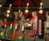
One thing I have found is that the Clean channel selection setup is not the same as the standard online schematic for the 2210 shows. Channel selection is normally done by simply shorting the signal to ground at either the input of the Clean channel at its Volume control wiper, or at the input and output of the hated diode clipping stage at its Gain and Volume wipers. At least "shorting to ground" is the intention but a BJT behind a cap with no DC on its collector is going to do an appalling job of that, as we know! My own 2210 is a '89 version so is pretty late in the run and the Clean channel switching is not performed quite as standard. C40 on the schematic is missing. It's actually labelled C38 on the PCB. The Clean channel is muted by handling the wiper of the Bass control instead via a 220nF cap attached under the board between the IC and the pot. You can easily see it in the picture in the top left with the yellow sleeved legs. It could be someone's previous mod of course but this sort of thing is not unusual in the lifetime of a product run so I wondered if anyone knows whether this is a genuine Marshall production line mod.

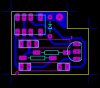
If there is any interest and I'm not dragging up old news which is long dead and gone I will post details of the mods once they are done. I can share the PCB, (1"x1" single sided for diyers), and details of how to improve the control and remove that hated channel bleed. It really is down to the nasty way the Master Volume and Channel selection have been implemented and not due to crosstalk or anything as complex as that.
 

Attachments

  • JCM800 PCB Tracking Component Overlay.jpg
    JCM800 PCB Tracking Component Overlay.jpg
    922.2 KB · Views: 108
Last edited:

South Park

Well-Known Member
Joined
Sep 14, 2019
Messages
4,045
Reaction score
3,938
Nice job not to wild about channel switching to old school. Its great you are working on this you should come with a circuit board with all this stuff on it. I can see the need for new boards for amps in the future
 

bordonbert

Member
Joined
Jan 24, 2015
Messages
59
Reaction score
15
Here is a working sketch of where I'm going with this. I have had this all breadboarded and tested on its PCB. I'm fitting it all in now.

Footswitch control schematic.jpg
 
  • Like
Reactions: Rej

bordonbert

Member
Joined
Jan 24, 2015
Messages
59
Reaction score
15
The relay is an Omron GK6 series 3V DPDT Non-Latching (not the "U" designation) which is tiny so the whole PCB is only a touch under 1"x1". The MOSFETs are any old general purpose type but the 2N7000 is cheap and accessible and has a nice low Ron which we want. The LED can be pretty much any Red/Green type as long as it has a Common Anode and not a Common Cathode. 2V/2.2V is about the mark but the values can be trimmed to take on any general type. The mounting of all of this is very simple and I will post pics once I have it finished.
 

bordonbert

Member
Joined
Jan 24, 2015
Messages
59
Reaction score
15
Can't edit to update the layout mapping. Have to post this again. It now has the valve connections on it too.
 

Attachments

  • JCM800 PCB Tracking Component Overlay.jpg
    JCM800 PCB Tracking Component Overlay.jpg
    361.6 KB · Views: 70

bordonbert

Member
Joined
Jan 24, 2015
Messages
59
Reaction score
15
I know this isn't a terribly popular type of topic but maybe someone can spread a little knowledge here as I have a query on historic stuff. I'm well on the way with my channel select mods. I have my own MOSFET driven subminiature relay PCB in place on the board and it works a treat. I have hooked it up to my own Red/Green LED mod too and that looks much more user friendly than Red/Off to my eyes. And each of those mods is very much easily reversible.

Things I have learned on the way:

First I found a number of contradictions (errors) in the usual schematic going the rounds. A minor irritation is that C40 in the schematic shows as C38 on my PCB. A bad one is that D4/D5 diodes in the control circuitry are labelled the wrong way around. D4 on the PCB is actually D5 on the schematic and vice versa. Worth bearing in mind as one needs to be removed and the other shorted out. (Ask me how I found that!)

Next I found the schematic does not tie up with my PCB in the Clean channel muting on Drive channel selection. It shows C40 (schematic) connecting to the Clean Volume wiper and V2a grid. On my PCB this is labelled C38 and connects to the junction of R5/R6 and the wiper of the Treble control. Ostensibly they will do the same job but there may actually be some subtle difference such as quieter changeover as the valve grid is a little more isolated from the grounding. My PCB had C38/40 missing completely and a long legged 220nF cap connected between C38 control side pad and the Volume control wiper just as the schematic shows it. It's an oddity I would like to tie down.

I initially started off by shorting out the caps from the control section to the channel pot wipers so the relay worked directly on pulling the signal to ground. That way there was no frequency dependence and the entire signal would be made silent. That is exactly what happened but, as I feared it might, it popped when the channel was changed. There is a tiny bit of leakage in the coupling caps between the stages which causes a few mV of DC around the 1Meg Volume pots. It wasn't disastrous but it was enough to make me reappraise and go back to using Marshall's isolating caps C11/C12/C40. That sorted the popping but left a very very small amount of bassy channel bleed when Gain/Volumes were maxed just as you would expect with caps. I am now going to try replacing the 22nF anode coupling caps for new, and fitting much larger PET caps for the grounding ones, (electrolytics will NOT do for this as they are generally pretty awful sounding and terribly leaky without a decent DC voltage to polarise them). These will be 5.6uF in place of the 0.22uF originals and a drop in fit at exactly the same size. That's the joy of modern components for you! More bang for your buck in a smaller package. While most of the other caps around do need to be high voltage types coming from the valve anodes, these 3 are only working on isolated sections of circuitry permanently held at ground potential. 50V DC is fine here and RS Components have them in at about 40p. No contest, they are going in tomorrow when they arrive.

I've put up a pic of the installation. It doesn't show every detail but it should give an idea of how it fits in.

So to my request...

I recently came across someone's recollection of a mod which had already been applied in this area and I would like to know details if anyone can help. It's an apparent Marshall in house mod that was applied into the production run around '87. I don't know what it was but, as I said, I did find on my own PCB that the signal grounding point for the Clean channel muting was not what the schematic showed. The schematic shows C40 pulling down the Clean channel Volume wiper and V2a grid. On my PCB C40 (labelled C38) connects to the Treble wiper and it is missing and a long legged cap has been fitted on the PCB underside connecting to the Volume wiper as the schematic shows.

The schematic usually found online, at least the only one I can find, has a Revision 1 dated 06/03/87, (that's an English dd/mm/yy format), and a Revision 2 dated 18/05/88. This should be the schematic after the mod was applied and it seems to match up with the flying cap mod (bodge) on my PCB. Does anyone know any more info on this aspect? It's an ear worm for me. I just need to lay it to rest to be sure I am getting the best out of my new setup.
 

Attachments

  • JCM800 Modded PCB.jpg
    JCM800 Modded PCB.jpg
    108.7 KB · Views: 71
Last edited:

RickyLee

Well-Known Member
VIP Member
Joined
May 22, 2010
Messages
10,295
Reaction score
3,709
Location
SoCal U.S.A.
Wow. You have quite the project going for sure. You obviously are much more schooled in electronics theory than I could ever hope to understand.

On my two '88 2205's, I know I did run into some oddities with the caps on the underbelly of the PCB. My memory can not recall specifics, but I know we had some discussions on it here in the forum.

Both my amps actually seem to switch well enough for me. The reverb stays put in the mix while switching channels, unlike the DSL/TSL amps, so that is a big plus for me.

I have no experience on the variations of the 2210 though. I do have a later version 2210 PCB in the stash, and I think it was missing that C38.
 

bordonbert

Member
Joined
Jan 24, 2015
Messages
59
Reaction score
15
Hi Ricky. Thanks for the comments. 40 years of designing electronics in industry does give you a bit of a perspective and this is baby stuff believe me. I've seen a few of your posts as I have browsed. Keep that fine open mind of yours and the questioning approach my man, it is a rare rare thing in this internet forum age! ;)

Ok, I'll round off this topic unless anyone has any questions I can help with. I have the whole setup in place now and the amp is up and running.

I have implemented the Red/Green LED mod using the MOSFET driver in place of Tr1 BC184. I think you should have enough info in previous posts to do this yourself if you feel like it though to do it as I have relies on going the whole hog and using the relay PCB. I could tell you how to implement this as a standalone mod if anyone asks for it. Just post it here and I'll try to oblige.

I have my own relay PCB in place as you can see and it is now switching channels immediately and absolutely silently with no hint of a pop. It is ridiculously cheap if you can make the PCB yourself and is so simple it could even be built on a bit of stripboard if you must. I'm used to working with custom PCBs for many years so I stick to doing things that way. I would suggest to anyone else who plays around with this area that the idea of shorting out the pot wipers direct to ground to mute either channel is not the way to go. I tried it and found, as I suspected, it can lead to significant pops on changeover and it is unnecessary. Stick to going through the existing caps C11/C12/C38(40) as this works as it should taking into account their values as described in the next paragraph.

My amp was not really a problem one initially being an '89. Though I could detect some clear bleed through it was way down on normal signal levels and would only possibly come into play at very low volumes. Remember, the level of bleed through is not dependent on the Volume control of the selected channel. It is more or less a constant unless the Volume control of the muted channel is set to very low levels. After these mods there is now absolutely no sign of it at all in either channel at any volume. That's with the MV maxed, either channel selected, the selected channel Volume/Gain turned down to 0 and the other silent channel Volume/Gain maxed. Anything that you hear under those circumstances is bleed through from the muted channel. I hear absolutely nothing. I really think the main reason I have now achieved absolute silence is that I have swapped out the C11/C12/C38(40) 0.22uF caps for 5.6uF ones. Any value above the original 0.22uF will help, the higher you can get the better, up to about where I ended up which eliminated it completely. That is 25x as large and means the frequency breakpoint where that bleed begins to show comes down by a factor of 25x. For anyone trying to fix a real bleed through problem I would recommend just the single step of upping those three caps as a simple starting point.

The relay will help too but I have not tested how much better it makes it. I just know from experience that the transistors which are used to pull the lines down cannot work as well as they should under the conditions in which they are being used. They have no polarising collector voltage and must work with signals on their collectors which go negative. That's not how BJTs should be used at all. It obviously isn't dangerous to them but it won't be a job well done. When Marshall implemented this it was pretty much a cutting edge idea and BJTs were just about all that was available to implement it cheaply. Nowadays they are the wrong tool for the job.

You MUST get the right type of capacitors but it MAKES NO DIFFERENCE WHICH COMPANY MAKES THEM. THERE ARE NO MAGIC NAMES HERE!!! Do not get electrolytics as they must work without a polarising voltage and they are problematic when doing that. Do not get 'X2' type mains rated caps even though they are common (and more expensive), they are not made for this job. Get simple low voltage polyesters like the link here:

https://www.ebay.co.uk/.../R60CF4560506AK.../202670159877...

Look for polyester or PET and you should be alright. They may come in different shapes, that isn't a problem. Also try to get caps with a 10mm lead pitch as these will go direct into the original holes. You can see that mine were a tad wider so C38 did not quite sit flat to the board thanks to the nearby pot but that is no problem at all. I got my own from RS Components in the UK who are mainly suppliers to the industry but you would need an account to buy there unless you have one of their rare retail desks near to you. In the US you will have your own sources of course. From RS they cost 0.46p each delivered. You will pay more from a more hobbyist targeted supplier but you can judge it accordingly.

I also chose to stick with the Clean channel muting point that my own amp was originally set up for as it works perfectly. I believe that early amps may have had the Treble pot wiper as their muting point. C38(40) on the "JM83" code PCB is connected to that as you can see in my attached photo. My own amp had C38 to that point missing and a manually fitted cap under the PCB leading to the Volume pot wiper from the inboard terminal of C38 instead. I think this is a Marshall in-production mod to later models which may have been why my own was not too bad. I cut the PCB track a couple of mm after C38 on the way to the Treble pot. If you do this neatly and SMALL you can just bridge over it with solder if you ever need to. It then means the holes for the cap can be used for your own replacement and you can add a small light flying lead after it to the Volume pot.

So I think that is basically it. There is an involved relay PCB mod, a simpler Bi-colour LED mod, and a very simple cap substitution solution to help with channel bleed. It sorted the issue for me totally.
 

Attachments

  • JCM800_2210_Splitch_Finished_Channel_Selection_Mods.jpg
    JCM800_2210_Splitch_Finished_Channel_Selection_Mods.jpg
    611.2 KB · Views: 61
  • jcm800_2210_splitch_channel_select_pcb_display.jpg
    jcm800_2210_splitch_channel_select_pcb_display.jpg
    99.8 KB · Views: 49

RickyLee

Well-Known Member
VIP Member
Joined
May 22, 2010
Messages
10,295
Reaction score
3,709
Location
SoCal U.S.A.
Excellent work man.

Yeah, I will keep this post in mind if I get the itch to dig back into my '88 2205 #1 which I already did some voicing experimenting on. My '88 2205 #2 is bone stock and I was actually considering putting it up for sale a few times. But, just can't get myself to let go lol. Plus, I like having a stock one to compare to #1 in case I decide to get back inside of it for some experimenting . . . .
 

bordonbert

Member
Joined
Jan 24, 2015
Messages
59
Reaction score
15
Interesting update. Just had a response back from good old Joanna my really helpful contact at Marshall.

There never was an in house mod applied to the 2100 PCB layout for channel bleed so the flying cap I had looks like someone else's idea of improving things. It looks to me like it was a good one as it seems to work perfectly once I had increased the cap value. She also said that, thanks to the 2100SLX with its extra valve, the PCB had to be renumbered a couple of times which could account for the C38/C40 confusion we see in the schematic and the wrongly labelled D4/D5.


IMPORTANT EDIT: I got the last bit about the diodes wrong, can't think how. Maybe it's with flipping the PCB and reversing it in my head too many times late at night. Maybe it's just senility or crass stupidity. :erk: The schematic shows D4 connecting to IC1 pin 9 and D5 connecting to pin 6 (not actually labelled on the diagram). Though I have said it is an error, this is actually correct!

You need to lift one leg of D4 to remove it from its connection to IC1 pin 9 and short across the pins of D5 to connect direct to pin 6 (not actually labelled on the schematic). The odd thing is that the circuit will work perfectly even if the diodes are treated incorrectly but the drive to the two MOSFETs is not evenly balanced and protected as it should be.

My apologies, crisis over. Forget I ever mentioned those diode numbers. :nuts:
 
Last edited:

RickyLee

Well-Known Member
VIP Member
Joined
May 22, 2010
Messages
10,295
Reaction score
3,709
Location
SoCal U.S.A.
Interesting update. Just had a response back from good old Joanna my really helpful contact at Marshall.

There never was an in house mod applied to the 2100 PCB layout for channel bleed so the flying cap I had looks like someone else's idea of improving things. It looks to me like it was a good one as it seems to work perfectly once I had increased the cap value. She also said that, thanks to the 2100SLX with its extra valve, the PCB had to be renumbered a couple of times which could account for the C38/C40 confusion we see in the schematic and the wrongly labelled D4/D5.

I am confused about the info on the 2100 and SL-X and how it relates to the Split Channel 800 series? Did you mean 900 2100 model amp, or is that a PCB number? The JCM 900 2100 MK III and SL-X amps are not channel switchers and completely different PCB's if my memory is correct.

Maybe I missed something above you wrote about?
 

bordonbert

Member
Joined
Jan 24, 2015
Messages
59
Reaction score
15
Sorry, I can't shed any real light on this Ricky, I can only go by what Joanna at Marshall told me. I'm no expert on the later amps, (nor the plethora of Marshall models in general). My interests mainly run to understanding the innards of the ones I own as that is my own speciality and how they give the sound that they do in using them. There are huge gaps in my amp knowledge between my late '60s SL100 and '89 JCM800 and JVM205H.

She wrote: "The circuit boards on the 2100 then the 2100SLX which had four pre amp valves instead of three, the circuit boards were re-numbered on several occasions as the same circuits were use on both versions, this will give your discrepancy with the C40/C38. There was never a modification with regards to channel bleed."

I wouldn't be surprised if the 2100SLX development project had started off with the existing schematic of the 2100 with that being edited as work on the new model progressed. I've seen stuff like that done before. It's always easier to start from something you have rather than from scratch with drafting. The downside is that the numbering can become very confused. You probably know already but the usual way to do this is to take your finalised schematic and start at the top left numbering the components in a top to bottom, left to right pattern. You can always tell a schematic which has had revisions as you can see the pattern exists but there are a number of out of step components in there or even some numbers missing altogether. It almost looks like Marshall prefer a system where they do this on the PCB rather than on the schematic then tie up the two afterwards. Mind you the Marshall PCBs from this era are not really PCBs at all. They are a halfway house and are almost a handwired layout placed on a PCB rather than turret board. Thank God they moved on and started optimising layouts to actually buy into the benefits of PCBs.

As I said, my own PCB was the JM83 version with that code etched in copper. I had assumed that was the standard PCB for that period and would have carried any mods that Marshall had made. In truth the SLX didn't even come into my mind. It is too much to expect a company to come up with a revised PCB every time a slight improvement is made if it can be implemented easily as a manual mod on the existing one. I do understand that the SLX would have to have a totally new PCB as the circuits are nothing alike so the comment about the discrepancey with C38/40 puzzled me too. It isn't a deal breaker though as we know what the circuitry should be around that area. Also there is no conflicting cap to confuse which is which, there is no C40 on the PCB nor a C38 in the schematic. It's just one cap and it's labelled C38 on the PCB and C40 in the schematic.
 

Thermionick

New Member
Joined
Nov 16, 2020
Messages
3
Reaction score
2
On the clean muting question, I've just been working on a 4212. The muting on that PCB is done by a 220nf cap to the bass pot wiper. This is not a mod but part of the PCB. With anything like a half decent size signal 4Vpp at that point I see the CA3046 clips the signal, especially on transients due to the asymmetrical currents through the CA3046.
 
Top