milfordcubicle
New Member
- Joined
- Mar 24, 2021
- Messages
- 10
- Reaction score
- 8
Hi, this is my first post on the forum, and probably not my last! I have a 1990 JCM900 4500 DR that we've owned since ~1994, purchased used. This model has to JMP50B power stage board and came stock with EL34s (no reason to think this was modded from 5881 given the confirmed year of the amp, screen resistor values and pins 1-8 jumper). I recently changed the tubes and went to adjust the bias, realizing it was between 7-8ma on each tube. I maxed out the bias pot and could get ~20ma best, so I swapped out the 56k bias range resistor (R30 on this board) to a 47k and that allowed me to adjust the bias to ~36ma on one tube and ~37ma on the other. Plate voltage on both is reading ~450 volts, so these are biased at a safe 65% or so.
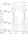
Amp sounds great but I noticed that pin 5 on V5 (control grid) has a 1/4 watt 2.2k resistor soldered to the pin. That pin then runs to an orange wire to R27, a 1.5k resistor (the "swamp" resistor, I believe). V4 does not have any resistor on pin 5 and has a green lead running to R24, also a 1.5k resistor. The schematic properly identifies these 1.5k resistors on the board and the green and orange leads are correct, but one of the tubes has this extra 2.2k resistor in series with the 1.5k. The schematic does not show an additional resistor in series. The solder job doesn't look original on the V5 pin 5 2.2k resistor but I wouldn't actually know.
I'm still new to this and I have read that it can be beneficial to run up to 5.6k swamp resistors on pin 5 of EL34s, but I would expect the resistance on both control grids to be symmetrical (currently, it is 1.5k on pin 5, V4 and 3.7k [1.5k + 2.2k] on pin 5, V5). I have no reason to believe this is affecting performance, but I don't know why this extra resistor is there. Any suggestions?