pete mac
New Member
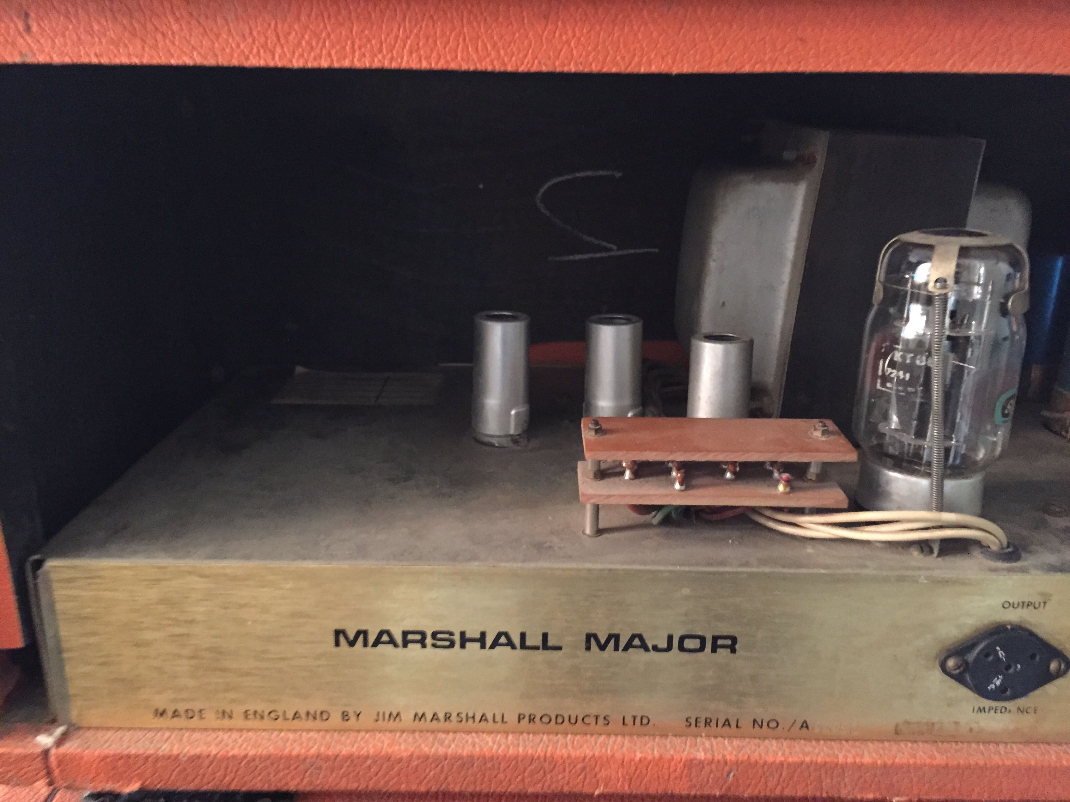
The output taps on my '72 go to a 'christmas tree' (?) termination to very thin screened cables to the impedance selector.My '74 output wires go direct to the selector.I found a comment somewhere online about the major output wires needed routing outside the chassis to stop interference/feedback.I'm restoring and making more reliable a couple of majors.The thin screened cable doesn't look capable for the potential current especially on the 4 ohm winding.Was the screening system/christmas tree dropped later as not needed/caused transformer failure ? A bit of a long shot after many years but someone might remember !
Thanks
Pete
Thanks
Pete