• We are looking to make improvements to the Classifieds! Help us determine what improvements we can make by filling out this classifieds survey. Your feedback is very appreciated and helpful!

    Take survey

Simple Attenuators - Design And Testing

  • Thread starter JohnH
  • Start date
  • This site may earn a commission from merchant affiliate links like Ebay, Amazon, and others.

IvanMan

New Member
Joined
Dec 6, 2018
Messages
6
Reaction score
3
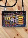
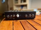
No, it's aluminium. In the attachment you can see the external, with the wings that help dissipation (all the resistor are mounted on the ceiling).
PS The picture is my old realization, now internally I changed to M220180109_230253.jpg
 
Last edited:

lordjester

New Member
Joined
Jan 27, 2022
Messages
8
Reaction score
10
Hi John,
I finally build an M2, with 3,5/7 dB Stage and a bypass switch. I did a few tests and I´m really impressed, it works perfect! I have tried a few attentuators over the yeras, my first one must be around 1982, a Tom Scholz Power Soak. It cuts treble, from the moment it is one, as far as I remember. I tried Weber Mini Mass, I sent it back immediately, I tried Toneking Ironman, same. I liked the UAD OX Box, but it is too expensive for my taste, because I really don`t need the speaker simulation stuff...I like the THD Hotplate, although most people don`t, as long as you don`t use the Pot. Up to minus 16dB without the pot, it works not bad. But the M2 is really much more natural to me and I probably will use it all the time. I think about building a road version, because on a regular gig, I problaby don`t need the extreme attenuation. So it would be nice to have small box, with maybe only one or two stages.
Thanks a lot for sharing your knockledge, I appreciate it alot!!
 

Attachments

  • IMG_0010.jpeg
    IMG_0010.jpeg
    610.4 KB · Views: 59
  • IMG_0013.jpeg
    IMG_0013.jpeg
    485.9 KB · Views: 58
  • IMG_0015.jpeg
    IMG_0015.jpeg
    401.1 KB · Views: 58

JohnH

Well-Known Member
Joined
May 31, 2008
Messages
6,156
Reaction score
5,062
Location
Wilton NSW
Hi @lordjester , thanks for posting and congrats on getting it all together. I'm really happy it works well, and I see it has several of the extra features such as 3rd output for 16 ohm, line-out, and 3.5/7 db front end. Ill be interested in your comments on how those are, in due course. Thanks also for your comments in relation to the other attenuators, which are very encouraging for what we are doing here!
 

lordjester

New Member
Joined
Jan 27, 2022
Messages
8
Reaction score
10
I really wanted to build an "all options version", everything works fine. I did not really check out the 16Ohm output and the line out, yet.
For live playing, I would not need all this options. I probably like to build a smaller version, only input and one output, no bypass, no line out, without the -14db stage, and maybe even with only -3,5 reactive stage, instead of the the switching version from 3,5 to 7dB.
 

JohnH

Well-Known Member
Joined
May 31, 2008
Messages
6,156
Reaction score
5,062
Location
Wilton NSW
I thought Id put up something to try to explain what the switchable -3.5/-7db front end is expected to do.

These are analysis results, not physical testing, but so far of these designs, the calcs have given a fairly good prediction

Red is an unattenuated 4x12 cab, Blue is what we expect from the same cab after the attenuator, and Green is what the amp sees feeding into the attenuator. All traces a matched for volume so they can be compared for tone. Ideally they would all overlay, though with M2, we don't show the amp the low resonance peak.


M2 with 3-5db 7 db front end 220321.jpg

The upper trace is an M2 running at -14db, using the basic -7db Stage 1 and another -7db stage. It gives a very good tonal match from Red to Blue, as it does at other settings too, and above the low bass, Green follows as well so the amp is responding accurately.

The Middle trace is just Stage 1, now set to -3.5db. It also does a good job of following the intended curves.

The Lower trace is with stage 1 set to -3.5, then a -7 and -3.5 stage to make -14db, (as in the top trace). Still Red and Blue are quite close, but the green trace is fallen off the ideal. Basically the amp is not seeing a full reactive load. It will still work OK, and with clean sounds it will likely sound fine, but the extra dynamics coming from a pushed amp may be diminished. Compare this to the top trace, which is a better looking version of -14 db.

What's happening is that at -3.5db, some extra reactance from the speaker is reaching through to the amp, giving it about the right amount, whereas with stage 1 at -3.5, and then more following attenuation, this doesn't come through.

I don't know if these differences can be heard, but Id expect that they sometimes could be. So, it shows how the intent of adding the optional switching to make -3.5db at the Stage 1 was really just for getting that one extra setting of -3.5, instead of starting at -7db. At -7db and below, I was expecting it to be a bit better when set to the base setting with a -7db Stage 1, although it can be tried either way.
 
Last edited:

Gene Ballzz

Well-Known Member
Joined
Feb 19, 2013
Messages
4,697
Reaction score
6,521
Location
Las Vegas, NV
So @JohnH , is the signal you are virtually applying for your sim testing considered to be white noise, pink noise, or……….?
Just Curious?
Gene
 

JohnH

Well-Known Member
Joined
May 31, 2008
Messages
6,156
Reaction score
5,062
Location
Wilton NSW
So @JohnH , is the signal you are virtually applying for your sim testing considered to be white noise, pink noise, or……….?
Just Curious?
Gene

Its basically a frequency sweep, done in a humongous spreadsheet, but the result is based on the same type of assumptions as would go into a SPICE model. It is based on each frequency being the same amplitude. So its an informative design tool for comparing options, but doesn't capture the relative levels of typical real music signals
 

TomBallarino

New Member
Joined
Jan 25, 2021
Messages
13
Reaction score
13
Hi @TomBallarino , thanks for posting that. It looks really great and you have pushed the design forward in a few areas. So Id love to ask a few questions, which will help others:

How are you finding the results from it so far?

I'd really like hear about your impression of the difference between having the bass resonance circuit in or out, (ie keeping L1 in but shorting L2 and C1)

Whats your line-out sub circuit?

What values did you work out for the -1.75 stages?

What fan did you use and what's the circuit for it?

thanks agsin for posting!
Hi @JohnH ,

I promised I will return back when I used my build in a real-life situation, which I did last weekend. I played a live-gig with my version of the M3 (with option to short out L2/C1), and a controllable -3,5dB solo boost
The boost worked very well and did what it should do, the volume bump was exactly what I needed for soling.
While sound check my bass player and I switched back and forth the "reactive" switch which shorts the extra L2/C1, and could not agree if or what did actually change in the sound on the stage, so the differences are really (as many have predicted/noticed) very subtle. So for live-purposes I will build the M2 version, as the extra inductor and capacitor (when done in specs, e.g. foil capacitor) are a heavy addition to the device.

Amp was a JCM800-2204 clone with KT66 output tubes and the master pretty wide open.
 

JohnH

Well-Known Member
Joined
May 31, 2008
Messages
6,156
Reaction score
5,062
Location
Wilton NSW
Thanks @TomBallarino , that's great feedback. It looks like the extra resonance circuit in M3 is not needed then, unless perhaps when used for silent recording with no real speaker.
 

EC Strat

Active Member
Joined
Jan 6, 2020
Messages
108
Reaction score
184
Thanks @TomBallarino , that's great feedback. It looks like the extra resonance circuit in M3 is not needed then, unless perhaps when used for silent recording with no real speaker.
JohnH,

Forgive me as i'm REALLY late to the game here and just now jumping onboard the gravy train. I have a JTM 45 RI and i'm interested in building your M3 design - is there a list of parts that i need to get started that i can order from? I'm at square 1 here on this.

I've gotten pretty good at soldering electronics in my guitars and i can follow a schematic reasonably well but i've never tackled anything like this before.
 

JohnH

Well-Known Member
Joined
May 31, 2008
Messages
6,156
Reaction score
5,062
Location
Wilton NSW
Hi @EC Strat and welcome to our thread. There has been a few parts lists through the thread, but most builders buy from the suppliers that work best for them depending where they are, and so the ordering list ends up a bit different. Also whether to get brand-name resistors shipped quickly, or order from eBay in China, which are fine but take a long time,

A few things to be decided:

1. What ohms value from the amp do you want to use? you can build these for 4 or 8 or 16 ohms. (its also possible to add a few parts to deal with different input ohms, but best to pick one)
2. What speaker ohms do you want to use? You can use 4, 8, or 16 with an 8 ohm build, or 8 or 16 with a 16 ohm build. Its best to match for your main use.
3. What is the power of the largest amp that you might want? I think a JTM45 is close to the VM that I have, and 50W spec is good on that
4. Our basic design is M2, and it works great for any use where you are playing through a guitar speaker. M3 adds two more parts, to capture the bass resonance at the amp. But, as described by Tom above and others, it doesn't make a significant difference when used through a cab because the design is set up so cabs develop their own natural resonance. It could be useful if you want to do silent recording with no cab and a line-out into a cab-sim or IR box. The parts to go from M2 to M3 are quite bulky and expensive, so its a choice to be made. Given some planning, you can add these later to an M2 to make it M3, there's no other changes. So, is silent recording through a Line-out something youd like to have? Do you need a line out?
5. What will be the use of the attenuator? If its for home or studio, the base designs work well, which start at -7db which is a factor of 1/5 on power. A 50W amp becomes 10W, or less. A few builders have wanted a smaller reduction for loud gigs, so we can add a switch to provide -3,5db setting.
6. You can build in a socket to add a footswitch to make a level change for solos, if needed.

What do you think about all of that? The best advice is to build it as simple as possible to meet your needs. Its not expensive and keeping it simple makes for a simple and reliable wire-up and easy use.
 

Gene Ballzz

Well-Known Member
Joined
Feb 19, 2013
Messages
4,697
Reaction score
6,521
Location
Las Vegas, NV
@JohnH beat me to it, almost word for word! John and I go back & forth, round & round on the following opinion: If you have 16 ohm taps on the amps you plan to use, I recommend the 16 ohm version. The 16 ohm M2 exhibits less compromise when using an 8 ohm cabinet that the 8 ohm unit does with a 16 ohm cabinet, if that makes any sense. It also allows you to run the unit at full attenuation in parallel with the speaker/cabinet (with amp tap set to 8 ohm) for a -3.5db cut. If you want to run parallel with an 8 ohm unit, your amp needs to have a 4 ohm output tap available! While there are design work arounds and add ons to get around these points, I will reiterate John's comment: "The best advice is to build it as simple as possible to meet your needs. Its not expensive and keeping it simple makes for a simple and reliable wire-up and easy use."

I will add that good heat sinking of resistors and good flow thru, convection ventilation is crucial for use with any amp above 20 watts! Also, all metal used in construction should be aluminum. Isolated, CLIFF UK style jacks are also important, to ensure that the enclosure/chassis does not ever become part of the circuit, as there is no ground, per se, simply positive and negative.

Have A Fun Build!
Gene
 

EC Strat

Active Member
Joined
Jan 6, 2020
Messages
108
Reaction score
184
Hi @EC Strat and welcome to our thread. There has been a few parts lists through the thread, but most builders buy from the suppliers that work best for them depending where they are, and so the ordering list ends up a bit different. Also whether to get brand-name resistors shipped quickly, or order from eBay in China, which are fine but take a long time,

A few things to be decided:

1. What ohms value from the amp do you want to use? you can build these for 4 or 8 or 16 ohms. (its also possible to add a few parts to deal with different input ohms, but best to pick one)
2. What speaker ohms do you want to use? You can use 4, 8, or 16 with an 8 ohm build, or 8 or 16 with a 16 ohm build. Its best to match for your main use.
3. What is the power of the largest amp that you might want? I think a JTM45 is close to the VM that I have, and 50W spec is good on that
4. Our basic design is M2, and it works great for any use where you are playing through a guitar speaker. M3 adds two more parts, to capture the bass resonance at the amp. But, as described by Tom above and others, it doesn't make a significant difference when used through a cab because the design is set up so cabs develop their own natural resonance. It could be useful if you want to do silent recording with no cab and a line-out into a cab-sim or IR box. The parts to go from M2 to M3 are quite bulky and expensive, so its a choice to be made. Given some planning, you can add these later to an M2 to make it M3, there's no other changes. So, is silent recording through a Line-out something youd like to have? Do you need a line out?
5. What will be the use of the attenuator? If its for home or studio, the base designs work well, which start at -7db which is a factor of 1/5 on power. A 50W amp becomes 10W, or less. A few builders have wanted a smaller reduction for loud gigs, so we can add a switch to provide -3,5db setting.
6. You can build in a socket to add a footswitch to make a level change for solos, if needed.

What do you think about all of that? The best advice is to build it as simple as possible to meet your needs. Its not expensive and keeping it simple makes for a simple and reliable wire-up and easy use.
johnH - thank you for the lengthy reply!

1. 4 and 8 Ohms
2. I use two cabinets, both 8 ohm cabs wired in parallel. so at home, the amp sees 4 ohms and gigs 8 ohms ( i only use 1 cab for gigs. - too much shit to carry). Would want a 4 and 8 ohm switch
3. JTM 45 i believe is a 30 watter
4. M2 design will be perfect
5. home and gigs - would like a - 3 and 5 db, the 7 db and i think i saw one of yours have a -14 db as well? Question, can you run the attenuator will all of the switches thrown in series for a total of -31 db?
6. this would be cool to add and i would like to add it.

What are the parts that i'll need and which suppliers do you tend to use? I'm thinking i'll just hit the mojotone website and go shopping. they've already got everything at a one stop shop.
 

JohnH

Well-Known Member
Joined
May 31, 2008
Messages
6,156
Reaction score
5,062
Location
Wilton NSW
hi @EC Strat

Looks like it'll be an 8 Ohm M2 built to 50W then. This will work fine with 8 or 4 ohm loads, so one or two 8 ohm cabs. It has twin parallel outputs but no switch is needed for that. THe base M2 design also has a 3rd output, for using a 16 ohm cab with an 8 ohm M2, so you can ignore those parts if you dont want them.

The basic design starts with always on -7db, then switchable stages of -14, -7 and -3.5db. You can put those on or off in any combination, to get every 3.5db step from -7 down to -31.5 db. Post 1 on page 1 has some clips demonstrating.

3.5db is a very small step, so its a pretty fine level of adjustment provided. With your home and 4 ohm set up, I would think that running all that at -7db would be fine and you might well want more attenuation from the added stages.

For your gigs, it depends how you set up, how loud you get, do you mic the amps? etc. If you build the basic M2 starting at -7db, theres a neat work around that gives you an extra -3 db option. You use your amps 4 Ohm taps, put one 8 ohm cab in and in the other amp output socket, plug in the attenuator set to max attenuation with no cab. Now the box acts just as a load, taking half the power. There's no added parts for this.

Or, you can add a few parts to get a native -3.5db option in the box

On parts, if you go as above, minimal parts, Gene has a great layout on page 111 which you could use. A few others have tried it before,

You can get most of what you need from a major electronics supplier like Mouser or Digikey. The coil comes from places that sell loudspeaker parts, eg Madisound.com and Parts express in the US. is that where you are?

Can discuss more later
 

Gene Ballzz

Well-Known Member
Joined
Feb 19, 2013
Messages
4,697
Reaction score
6,521
Location
Las Vegas, NV
@EC Strat ,
MojoTone does not offer the aluminum case/heat sinkable resistors required for this build. Mouser is a good source, but DigiKey appears to even ship free to the EU, as well as US, if you order enough stuff, like the case also. Air Core Inductor coils in the US can be obtained from Madisound and/or PartsExpress. Parts and enclosure sourcing discussion starts in earnest around page #110 of this thread! A Hammong 1590D or larger is the minimum size for convenient fitment, especially if using the commonly/readily US/EU available resistors, but the cheaper resistors from chinesiawanoreanam have a smaller footprint and work OK, if willing to wait for them! Don't skimp on the rating of the switches. Minis are OK, but the larger full size ones from Carling have bigger lugs and are a bit easier to be neat with.
Happy Buildin'
Gene
 

EC Strat

Active Member
Joined
Jan 6, 2020
Messages
108
Reaction score
184
@EC Strat ,
MojoTone does not offer the aluminum case/heat sinkable resistors required for this build. Mouser is a good source, but DigiKey appears to even ship free to the EU, as well as US, if you order enough stuff, like the case also. Air Core Inductor coils in the US can be obtained from Madisound and/or PartsExpress. Parts and enclosure sourcing discussion starts in earnest around page #110 of this thread! A Hammong 1590D or larger is the minimum size for convenient fitment, especially if using the commonly/readily US/EU available resistors, but the cheaper resistors from chinesiawanoreanam have a smaller footprint and work OK, if willing to wait for them! Don't skimp on the rating of the switches. Minis are OK, but the larger full size ones from Carling have bigger lugs and are a bit easier to be neat with.
Happy Buildin'
Gene
OK so i just ordered all the parts. Had to go to a few different websites as some of the resistors were on backorder at Digikey - Mouser had those items for me. I ordered the Hammond 1590D Black aluminum box and got the .9mH 18 awg inductor air coil from parts express - the coil looks red but it says it's highly refined copper ?? Hope its the right one

Looks Ike I still need to order 2 out jacks and 1 in and a foot switch - I’m assuming the foot switch needs an in-Jack also? Where are good websites for those?

Deeply appreciate your help Gene and JohnH
 
Last edited:

donwagar

Well-Known Member
Joined
Nov 24, 2018
Messages
254
Reaction score
694
Location
Calgary, Alberta
The red coating on the coil is lacquer I think. Sand off the ends to connect them.

I bought my jacks from Mouser, I used 532-ACJS-PHOP (Mouser Canada, but I assume Mouser US uses the same numbers).

You'll want: 2 (speakers), 1 (from amp), and 2 for the footswitch, so 5.

I used a standard guitar pedal size aluminum box for the footswitch. I added an LED to it so I installed a power supply jack rather than use a battery.
 

JohnH

Well-Known Member
Joined
May 31, 2008
Messages
6,156
Reaction score
5,062
Location
Wilton NSW
hi @EC Strat

If you're doing the footswitch , then it needs a couple of resistors too. It amounts to another external attenuation stage. 3.5db seems to be the favoured spec. But its not part of the basic design. A few have been built and are reported to work well, out of many dozens of the basic M2's. I suggest to make space for a jack, but consider not wiring it in in the first build, in order to test the main parts. The jack for the footswitch needs to be a switched stereo jack, with 6 lugs, Cliff type
 

diego_cl

Member
Joined
Jan 10, 2021
Messages
57
Reaction score
31
I bought my jacks from Mouser, I used 532-ACJS-PHOP (Mouser Canada, but I assume Mouser US uses the same numbers).

I'm planning to build a 100W M2, so I would like to know if I should give it a try to the Amphenol Jacks or stick with Cliff UK.

I bought some Amphenol jacks from Tubedepot with solder lugs along with some tubes, back in november. But I think those jacks from Mouser "532-ACJS-PHOP" are Amphenol with pins for pcb mounting.
TubeDepot never sent them to me due to tubes shortage. I had to cancel the tubes so they could ship me the jacks alone (bad experience). I'm still waiting (overseas shipping).

What jacks are tougher, Amphenol or Cliff UK??
According to datasheets, Amphenol hold up to 10A and +1.000 cycles, while Cliff UK hold up to 5A and +10.000 cycles, but I don't know if datasheets are trustworthy when comparing 2 different brands.
 

EC Strat

Active Member
Joined
Jan 6, 2020
Messages
108
Reaction score
184
The red coating on the coil is lacquer I think. Sand off the ends to connect them.

I bought my jacks from Mouser, I used 532-ACJS-PHOP (Mouser Canada, but I assume Mouser US uses the same numbers).

You'll want: 2 (speakers), 1 (from amp), and 2 for the footswitch, so 5.

I used a standard guitar pedal size aluminum box for the footswitch. I added an LED to it so I installed a power supply jack rather than use a battery.
.
 
Last edited:
Top