• We are looking to make improvements to the Classifieds! Help us determine what improvements we can make by filling out this classifieds survey. Your feedback is very appreciated and helpful!

    Take survey

Simple Attenuators - Design And Testing

  • Thread starter JohnH
  • Start date
  • This site may earn a commission from merchant affiliate links like Ebay, Amazon, and others.

StratKat

New Member
Joined
Nov 10, 2022
Messages
2
Reaction score
4
Finally got round to building this. Thanks John H for your generosity in sharing the design. My previous experience with attenuators was with a Weber Mass and this easily surpasses it. I also have a Two Note Captor X. I find the Two Note to be a tad more transparent and has more presence but the fixed attenuation levels is inconvenient as I am using it with a non-master volume amp.

This thread is a great resource for anyone looking at an affordable solution. Hats off to you mate!
 

Attachments

  • 5D0A14E2-D1DF-4A47-92B7-2FFFD5126ED8.jpeg
    5D0A14E2-D1DF-4A47-92B7-2FFFD5126ED8.jpeg
    489.4 KB · Views: 53

Gene Ballzz

Well-Known Member
Joined
Feb 19, 2013
Messages
4,697
Reaction score
6,521
Location
Las Vegas, NV
Finally got round to building this. Thanks John H for your generosity in sharing the design. My previous experience with attenuators was with a Weber Mass and this easily surpasses it. I also have a Two Note Captor X. I find the Two Note to be a tad more transparent and has more presence but the fixed attenuation levels is inconvenient as I am using it with a non-master volume amp.

This thread is a great resource for anyone looking at an affordable solution. Hats off to you mate!

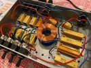
Nice job!
Enjoy,
Gene
 

crypto

New Member
Joined
Dec 19, 2022
Messages
2
Reaction score
0
First post here, I think. As usual kudos for everyone designing this. I was thinking a Weber - but the cost of importing a Weber mini-mass into Oz is crazy.

Want to fix the US economy - reduce the cost of international shipping - but that is a different story...

Anyway a couple of quick questions.


Variable L-Pads. I know it has been touched on elsewhere in the thread, and has been knocked back using an argument that the switched option allows specific tuning. I was thinking of a variable L-Pad after the first reactive stage, Is there detail - mathematical preferred, as to why this wont work as well?

Related to this. The resistive attenuation stages. They are like fixed L-pad attenuators but somewhat back to front. An L-Pad would exist as a voltage divider, this seems to reduce the current and then scale the signal. Have I misread the schematic?

Also related to this, there is a comment about input impedance being higher than you would think. Something about a conversation on TGP. I have been thinking that attenuation stages sit in front of the speaker with the property that each stage still presents the original output resistance (8, 16 etc Ohms) to the stage in front - effectively transparent. In other words I have been thinking input and output impedance of each stage is equal. But that does not seem to match the math. (My math could be wrong, wouldn't be the first time)

anyway thanks
 

StratKat

New Member
Joined
Nov 10, 2022
Messages
2
Reaction score
4
@JohnH
If I wanted to try the bypass capacitor across R2a with a 22 ohm series resistor, what power rating would the resistor need to have? Thanks again.
 

JohnH

Well-Known Member
Joined
May 31, 2008
Messages
6,155
Reaction score
5,062
Location
Wilton NSW
Hi @crypto
Thanks for your message and welcome to our thread

The conventional use of L-Pad pots is one of the main contributors to many simple attenuators sounding dull, particularly at low volume. The reason is that the output impedance seen by the speaker reduces to a low value as you turn down, damping the speaker and preventing the normal interaction of speaker reactive load with output impedance, resulting in the natural bass peak and treble rise being flattened, L-pads are only designed to approximately keep input impedance constant and usually offer no consistency in output impedance. Short of designing a complex customized pot, our design uses the sall switched steps so that output impedance and input impedance of the whole unit stay adequately consistent at all settings. Each stage is designed to maintain this. The maths is somewhat complex, but the result is a simple build.

For an 8 Ohm unit, we keep input impedance in the range around 7-10 Ohms and output impedance between about 18-20, and these values were determined after measuring a couple of my amps. Whats really interesting is if set up this way, the attenuators also work very well on different amps outside of this range, hence giving a great result with every amp that we know of (provided input Ohms are respected). If you want to investigate analytically, its easiest done with a SPICE analysis, which needs to include a credible reactive electrical model of a real speaker.
 

JohnH

Well-Known Member
Joined
May 31, 2008
Messages
6,155
Reaction score
5,062
Location
Wilton NSW
@JohnH
If I wanted to try the bypass capacitor across R2a with a 22 ohm series resistor, what power rating would the resistor need to have? Thanks again.
It's a bit hard to assess, since it will depend on how hard the amp is running in terms of distortion, and what frequencies are playing. If you try try this, my guess would be that half the rating of R2A with be ok.

But, presonally I've never seen a need to have this bypass cap since the circuit is designed to match the frequency response of a non-attenusted speaker.
 

crypto

New Member
Joined
Dec 19, 2022
Messages
2
Reaction score
0
If you want to investigate analytically, its easiest done with a SPICE analysis,
Yes I did a spice analysis and noticed there are differences in the spacing. Your model has more uniform seperation between curved. Haven't examined it in detail as yet though, I ran it up as more of a sanity test.

I am glad you said that your output impedance is around 18, there abouts because that's what my spreadsheet shows when I retro fit your values. So at least that is sane.

I have seen this sort of thing before, in the Fender Tweed Deluxe 5E3 tone stack. It will likely take some thinking to understand if that is a coincidence or not.

In the Tweed it is done to change the Plate Load and hence gain on the preamp before it. V1 on the Tweed, It pulls the Plate of V1 to ground, effectively rotating the load line on that preamp. It results in the 5E3 having variable gain on the first preamp a guitar signal sees.

Back in the 1950's there were no standards for how hot a guitar signal would be, so the 5E3 allows an amp to be matched to an instrument. Inadvertently building an overdrive into the amp....

If this is done to a power amp it would effectively reduce the gain on the power tubes - In this case though there is a transformer and the reactive stage between the power tube and this step, so very likely might be something else.

Anyway cool, let me have a think and readjust my spice models to see if I can understand the output impedance thing.
 

Guitar-Rocker

Well-Known Member
Joined
Mar 5, 2012
Messages
3,251
Reaction score
3,168
Location
Estero, Florida formerly from Indianapolis
hi @Guitar-Rocker
Thanks for your message. If you need to go significantly above 50W amp power, the next simple step is to go x2 for 100W. But rather than source a 200W one for R1, use two 100W in series or parallel. And add a fan.

If you want a setting thst delivers -3.5dB, then -7dB, -10.5dBetc... see design M4 which is linked from Post #1. The first reactive Stage 1 is swichable -3.5 to -7, for when you just want -3.5dB. You can omit thd -14dB stage if not wanted.


Thanks for the input John. I ordered a pair of 100W 60ohm resistors for R1, to get the resistance down to 30ohms when wired in parallel, but double the current capacity.
 

chas.wahl

New Member
Joined
Jan 18, 2020
Messages
26
Reaction score
4
Dear @JohnH ,
I'm about ready to put my quirky version of your attenuator on the build queue, based on M2v (with 3 input impedances) with the "gig" -7 or -3.5 dB base attenuation. In doing layout, it occurs to me that it would make use of the switching more intuitive to have the stages ordered either in ascending or descending order of attenuation -- my preference would be the latter, so that your "binary" logic would apply.

So, what I would like to know is whether the "base" stage could be shifted to a location in the layout right before the output jacks, without changing the sound of the attenuator. I'm attaching two images, the first is the basic schematic that I was working with (which I believe I've posted previously with other discussion/questions) and the second is with the stages reordered as per my question here.

If the reordered schematic is unworkable or inadvisable, then I'd be interested to know if I could simply swap the order of stages 2 and 4 to put them all in ascending order from left to right.

2023-04-02-M2Vgig.jpg

2023-04-02-M2Vgig-stages-reordered.jpg

If anyone would prefer PDFs, I can provide those too.

Thanks,
--
chas.wahl
 
Last edited:

TomBallarino

New Member
Joined
Jan 25, 2021
Messages
13
Reaction score
13
Hello everybody,

just wanted to throw in some measurement data I collected today. The unit under test was a basic m2 version with the following stages: -7dB(base), -7dB, -3.5dB,-1.5dB and two -1.75dB "solo boosts". I used the ARTA measurement software, a RME Babyface Pro interface, self-built 2x12 with Celestion G12H30 speakers, an SM57 microphone, and a Marshall-style EL34 50Watt power amp. The software does measure magnitude over frequency by using a "PN pink noise" input into the poweramp, and compares the level delivered to the speaker to the output level of the microphone. I measured the amp directly into the cabinet (M2 bypassed), the M2 between amp and cabinet with all toggles off (-7dB), with a -7dB(=-14dB) and the full attenuation available with this unit of -22.75dB. Here are the results:
m2-dampings.png
As you can see, the curves look very similar to each other. When you normalize the sound levels (by manually setting an offset), the result looks like this:
m2-dampings-normalized.png

To me this looks very good, and once again proves that the design of this attenuator is exceptional. I guess in this picture you can see the missing impedance peak in the lower frequencies (that the M3 version includes), as the frequencies below 200 Hz get boosted when the attenuator is active. (I think this is a good thing, as the perception at lower volumes changes anyways).

I did some comparisons of m2 and m3 version at full attenuation, but will have to render them out some time.

have fun,
Tom Ballarino
 

JohnH

Well-Known Member
Joined
May 31, 2008
Messages
6,155
Reaction score
5,062
Location
Wilton NSW
Hi @chas.wahl
It's important that the first reactive stage (with -7 / -3.5dB switch if you have it), is electrically first at the input and amp side. The resistive stages can be in an order electrically, we figured out it makes no difference.

Also, you are free to place switches physically on the panel in any order, even if different to the electrical order.

Hood luck with your build!
 

JohnH

Well-Known Member
Joined
May 31, 2008
Messages
6,155
Reaction score
5,062
Location
Wilton NSW
hi @TomBallarino
Thanks very much for those tests! They match with expectations, including the results at low frequency. M3 or M4 with the bass circuit may give a better looking match in the bass, but Id expect probably not much audible difference with a cab.
 

TomBallarino

New Member
Joined
Jan 25, 2021
Messages
13
Reaction score
13
hi @TomBallarino
Thanks very much for those tests! They match with expectations, including the results at low frequency. M3 or M4 with the bass circuit may give a better looking match in the bass, but Id expect probably not much audible difference with a cab.
Here is the comparison of the amp directly vs. a M2 and M3 version (both -22.75dB). As you predicted, the differences are not very big.
m2-m3-dampings-normalized.png
 

chas.wahl

New Member
Joined
Jan 18, 2020
Messages
26
Reaction score
4
Hi @chas.wahl
It's important that the first reactive stage (with -7 / -3.5dB switch if you have it), is electrically first at the input and amp side. The resistive stages can be in an order electrically, we figured out it makes no difference.

Also, you are free to place switches physically on the panel in any order, even if different to the electrical order.
OK, thanks, got it -- I suspected that might be the case, so I guess it's plan B (ascending order). I'd probably just confuse myself if I simply rewired the switches, so I'll just swap Stage 2 and Stage 4 (from input to output: the "V" input stage, then Stages 1, 4, 3, 2 to the outputs). That will put switches in - 3.5/-7.0 | -3.5 | -7 | -14 order.

Oh, whoops! One more question, based on your "M2 with 70-35 220126" sketch: do Stages 1 & 2 have some symbiotic relationship necessitating that 2 follows directly after 1? I ask this because there's that additional resistor R6A added to Stage 2, and I don't really understand what it's doing -- modifying the output of Stage 1, or the input of Stage 2, or both.

In other words, if I wish to move Stage 2 to follow Stage 3, and move Stage 4 to precede Stage 3, may R6A move with Stage 2, or does Stage 2 have to follow directly after Stage 1, full stop?

M2with70-35-220126.gif
 
Last edited:

JohnH

Well-Known Member
Joined
May 31, 2008
Messages
6,155
Reaction score
5,062
Location
Wilton NSW
Hi @chas.wahl
If you move stages 2, 3 and 4 to a different order, that's ok (so long as Stage 1 is first as noted before) Stage 2 doesn't need to go immediately after Stage 1 and all three resistors of Stage 2 should stay together.
 

JohnH

Well-Known Member
Joined
May 31, 2008
Messages
6,155
Reaction score
5,062
Location
Wilton NSW
hi @TomBallarino
That's very interesting indeed. The bass res circuit is making the lows closer to the non-attenuated. It's not a perfect match, because the Q of the bass circuit can't get as high as the real speaker resonance, especially with real readonably affirdable caps and coils

This is all related to the effective output impedance. Typical EL34 Marshall output impedances are often lower than the value I based the design on, which was based on the Kt66's in my VM, which is lower than on some other amps without negative feedback. But the reactive components help to compensate for these differences. (that's a really interesting outcome - hard to explain though!) for M2, at lower mids and above, and M3/4 at all frequencies.

But, I reckon it'll all sound good.
 

JohnH

Well-Known Member
Joined
May 31, 2008
Messages
6,155
Reaction score
5,062
Location
Wilton NSW
hi @TomBallarino
Just to complete the picture to learn the most from your tests. What sort of speaker set up are you using, and is it open-backed or closed-backed? The natural resonance of a closed back 4x12 is usually around 110 to 120 hz, while open backed is often lower, around 80hZ. In working out values for the bass res circuit, I was basing it on closed-back
 

TomBallarino

New Member
Joined
Jan 25, 2021
Messages
13
Reaction score
13
hi @TomBallarino
Just to complete the picture to learn the most from your tests. What sort of speaker set up are you using, and is it open-backed or closed-backed? The natural resonance of a closed back 4x12 is usually around 110 to 120 hz, while open backed is often lower, around 80hZ. In working out values for the bass res circuit, I was basing it on closed-back
@JohnH, I used a closed back, slanted, vertical 2x12 (selfbuilt, 15mm birch plywood), that contains 2 WGS Reaper 12" 16 Ohm in parallel. I falsely noted in the graphs above that Celestion G12H30 speakers were used, this was a mistake, they are in my other cabinet.
I did some impedance measurements beforehand, the result:
impedance.png

The impedance peak seems to be at aroung 114 Hz, but measurement resolution is not too great when using pink noise instead of stepping through (I tried the stepper mode, but it was unbearably annoying, even when I left the room:()

cheers,
Tom
 

firel7

New Member
Joined
Feb 1, 2021
Messages
3
Reaction score
2
@John H, First let me say thank you for all that you have done here! I am really excited to get this build underway! I have spent many hours combing through this thread to get a good understanding of this design. I do have a couple of questions though. Firstly on the air coil, I saw somewhere that 16 guage was called for in the 100 watt builds and I also thought I saw where 18 guage was appropriate. Could you please clarify? Does the resulting resistance matter? Secondly has it yet been determined there inthe circuit is the best place to insert a power circuit for the fan? I know the simple solution would be an external power supply however it would be convenient if it can be powered without a negative effect on the resulting signal. Finally I have attached a summary layout that I have worked through. Would you mind giving it a once over and review my work?
I have mocked it up in Solidworks in a 7.5 x 7.5 aluminum enclosure as that seems to fit the build well. I have attempted to keep the wiring runs as short as possible. If that layout looks good and would be useful for anyone I can certainly provide more views etc.
Again thank you for all your efforts on this!
Attenuator summary.jpg
 

Latest posts


Top