• We are looking to make improvements to the Classifieds! Help us determine what improvements we can make by filling out this classifieds survey. Your feedback is very appreciated and helpful!

    Take survey

Simple Attenuators - Design And Testing

  • Thread starter JohnH
  • Start date
  • This site may earn a commission from merchant affiliate links like Ebay, Amazon, and others.

Dogs of Doom

~~~ Moderator ~~~
Staff Member
Joined
Aug 2, 2012
Messages
32,992
Reaction score
55,788
Location
Los Angeles
hi @Dogs of Doom
Thanks, and I apologize and didn't mean to ignore your good question!

The way I think about these is: I start with the nominal power of the amp, and work out what steady-state share of that power would go into each component. Then to work out a spec rating, I first double it as an engineering margin, then I add another 50% to allow for overdriving the amp, and then round up to the nearest practical rating. So electrically, theres heaps of margin available for running it hard and continuously. Afet that, its down to good cooling, and thats where different builds may vary. But one thing we know is that none of these heat up quickly. Ive soak-tested mine with DC power and even a small build will take 30 minutes to get to maximum temperature. So anytime there's a break in the music, or a quiet period, less than thrash, the average power over a period of time is reduced.

We know that for a 50W build, 20W amps barely get warm, and some driven 50W amps get fairly hot, and would benefit from a fan and 100W amps with 100W builds need a fan if you want to drive the amp. We also know that once you get a reasonable 12V fan, running at 9V, it makes a huge difference to temperature. So Im confident that 100W into 100W attenuator, with a good fan, is OK

Continuous 180W? it depends on the build, electrically no problem but i dont think weve quite been there yet!

Does that help?
re: 180w... it was in asking about the unit Terry built, & what he spec'd the 100 watter at...

I ask because there are some 100 watt amp's that will push 180 watts at full bore. So, yeah, you have a 100 watt amp, going into a 100 watt attenuator, but, that's where my worry starts, because amp ratings are somewhat misleading & w/o a spec like that on the attenuator & speaker(s), it's all a guessing game, & IMO, failure at this stage is most detrimental...

Not holding anyone to the fire, as, like you say, we haven't gotten to that point, nobody's run it to it's limits yet.

You can't even get a definitive answer from the likes of Celestion, on how many watts their speakers are truly rated at. A while back, they changed the rating of their G12K-85 to G12K-100. In that case, they deemed that the speaker was actually a 100 watt speaker, but... you know that, there's usually an upper wattage tolerance. How much wiggle room is there on those now? 20% over rated? 40%? 60-80%? or do they fail at excessive 100 watts?

I'm just trying to get a feel for what these things are safe, as using under "normal" circumstances...

I haven't done it lately, but, in the past, I did many 5-6 hr stints. IDK if I'd ever have it in me to do it again, but, I'd like to know that my gear would hold up, if I did... :)...
 

Gene Ballzz

Well-Known Member
Joined
Feb 19, 2013
Messages
4,697
Reaction score
6,521
Location
Las Vegas, NV
since i'm being ignored, just curious. I know it's a 100 watt attenuator, but, will it handle say, 180 watts constant?

Like the 50 watt version. I'm using it w/ 20 watt amp's... perfect... I do have a couple 50 watt amp's, including an Ampeg 50 watt tube bass amp. I'm reluctant to use it w/ that, if it can't handle bass at say 80 watts...

@Dogs of Doom ,
When it comes to power handling ratings, one important factor is what frequencies are being pushed. Your above quote mentions handling bass at 80watts. Are you desiring to use an attenuator on that 50 watt Ampeg, while playing a bass guitar through it? Or are you simply referring to the bass frequencies produced by guitar when tuned down and "heavy metal chugging?" And yeah, that capability of 80 watts from a 50 watt amp is (I suspect) part of the reason @JohnH has designed with such a fairly wide margin for safety.
Just Thinkin'
Gene
 

Dogs of Doom

~~~ Moderator ~~~
Staff Member
Joined
Aug 2, 2012
Messages
32,992
Reaction score
55,788
Location
Los Angeles
@Dogs of Doom ,
When it comes to power handling ratings, one important factor is what frequencies are being pushed. Your above quote mentions handling bass at 80watts. Are you desiring to use an attenuator on that 50 watt Ampeg, while playing a bass guitar through it? Or are you simply referring to the bass frequencies produced by guitar when tuned down and "heavy metal chugging?" And yeah, that capability of 80 watts from a 50 watt amp is (I suspect) part of the reason @JohnH has designed with such a fairly wide margin for safety.
Just Thinkin'
Gene
I have a 50 watt bass amp, for bass guitar... That I play w/ a 4Kwatt Celestion speaker...

I just don't know, if I can trust, say, the M2 design on that amp, used that way. I'd be pumping serious juice through it. It has a master volume, but, I'd like to try & run it more like an SVT, w/ the master cranked, like I do the SC20 - which kills... but, the SC is a 20 watt amp, & regardless, if the 50 watt attenuator is rated at 45 watts, or 80 watts, it handles it just fine - not even a concern...

My worry is using it on a 50 watter, like the Ampeg & having something fry then blows a short back into the amp...

IDK how much power the Ampeg could put out at volume, it's my living room amp & I've never run it that loud... I'd definitely hook up a power supply to the fan...

edit: I do tune down & also have a 5 & 6 string bass. One 5 string is a fretless, that also has piezo, so it gets that upright vibe - low notes...

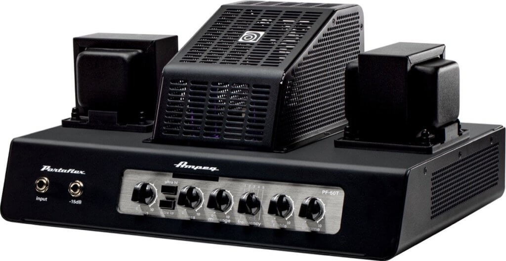
edit 2: this is the amp: PF-50T

Ampeg-pf50t-tube-bass-head-amp-1024x530.jpg
 
Last edited:

matttornado

Well-Known Member
Joined
Mar 14, 2012
Messages
1,900
Reaction score
1,510
@Dogs of Doom I used a giant 250 watt 30 ohm resistor for R1. I crank my 100 watt Superlead through it , on 10 for a few hours. It gets pretty hot but well within the resisistor's spec. I use a fan too justs for piece of mind though.
 

JohnH

Well-Known Member
Joined
May 31, 2008
Messages
6,155
Reaction score
5,062
Location
Wilton NSW
R1 is the component that takes the most share of the power. In principle, it takes 50% of the total. So take a 50W build, if there's 50 actual Watts, it gets 25W. But it's specced as 100W rating. So with margins and rounding up, it has a x4 factor, so plenty to allow for overdrive too. The same ratio applies if scaled up to a 100W build.

So if built well, there's nothing that is likely to suddenly 'blow'. Just a slow and steady build up of heat over a set. Fan cooling should control this. But, for a test, just touch R1 or the area of the case where it is. If you can touch it, it will be less than about 60 to 70 C. So maybe hot to touch but not hot in a tech sense. (eg at 100C you can not touch a metal pan of boiling water) . Actually, I've got an IR thermometer which is a perfect tool for this, but feel is ok if not.

I would trust one of our builds, with fan cooling, with substantial power much better than any commercial unit that I've seen.
 

Gene Ballzz

Well-Known Member
Joined
Feb 19, 2013
Messages
4,697
Reaction score
6,521
Location
Las Vegas, NV
R1 is the component that takes the most share of the power. In principle, it takes 50% of the total. So take a 50W build, if there's 50 actual Watts, it gets 25W. But it's specced as 100W rating. So with margins and rounding up, it has a x4 factor, so plenty to allow for overdrive too. The same ratio applies if scaled up to a 100W build.

So if built well, there's nothing that is likely to suddenly 'blow'. Just a slow and steady build up of heat over a set. Fan cooling should control this. But, for a test, just touch R1 or the area of the case where it is. If you can touch it, it will be less than about 60 to 70 C. So maybe hot to touch but not hot in a tech sense. (eg at 100C you can not touch a metal pan of boiling water) . Actually, I've got an IR thermometer which is a perfect tool for this, but feel is ok if not.

I would trust one of our builds, with fan cooling, with substantial power much better than any commercial unit that I've seen.

Well said, @JohnH , well said!
Still Attenuatin'
Gene
 
Last edited:

Tj99

New Member
Joined
Jan 31, 2019
Messages
3
Reaction score
3
Hey there people, where can I find the design for the M3 and M4? On post #1 there is only the schematic for the M2, or am I just blind?
 

JohnH

Well-Known Member
Joined
May 31, 2008
Messages
6,155
Reaction score
5,062
Location
Wilton NSW
hi @Tj99

it's on page 158, and in post 1 there is a link to it, just above 'Component values and power ratings'. But thanks, and I'll make it a bit clearer.

(One of the issues I have with updating post 1 is tbat there is a length limit on each post, so to get around that I've been linking from post 1 to other key posts)
 

AtomicRob

Well-Known Member
Joined
Feb 4, 2009
Messages
655
Reaction score
776
Location
California
I'm currently planning my next attenuator build to be a "solo boost" attenuator, with just stage 1 and stage 4 stage with footswitch, omitting the other stages. While planning this I've found a safer/simpler way to implement the footswitch. Maybe others have already thought of this too but I didn't see anything in this thread so I'll share my plan.

The M4 schematic on page 158 shows a footswitch option but sending the speaker-level signal out, through a stompbox, and back requires a nonstandard three-conductor cable. A relay in the attenuator avoids this problem. But I didn't want to require power in the attenuator either, and after thinking on this for a while I realized, oh... just send the power to the relay from the footswitch! The footswitch will always be on a pedalboard which of course has power. Just send 9vdc from the footswitch to engage the relay, using a plain old instrument cable.

Diagram below shows it with or without the switch (S4). It's a little simpler just substituting the relay for the switch, if you only ever plan to use it with a footswitch.

footswitch.png
 
Last edited:

JohnH

Well-Known Member
Joined
May 31, 2008
Messages
6,155
Reaction score
5,062
Location
Wilton NSW
I'm currently planning my next attenuator build to be a "solo boost" attenuator, with just stage 1 and stage 4 stage with footswitch, omitting the other stages. While planning this I've found a safer/simpler way to implement the footswitch. Maybe others have already thought of this too but I didn't see anything in this thread so I'll share my plan.

The M4 schematic on page 158 shows a footswitch option but sending the speaker-level signal out, through a stompbox, and back is risky IMHO and requires a nonstandard three-conductor cable. A relay in the attenuator avoids this problem. But I didn't want to require power in the attenuator either, and after thinking on this for a while I realized, oh... just send the power to the relay from the footswitch! The footswitch will always be on a pedalboard which of course has power. Just send 9vdc from the footswitch to engage the relay, using a plain old instrument cable.

Diagram below shows it with or without the switch (S4). It's a little simpler just substituting the relay for the switch, if you only ever plan to use it with a footswitch.

Or for an even simpler single-stage attenuator/boost (just stage 1) this same bypass could be used safely as long as it's wired so that it never disconnects the circuit path but only shorts R2A and disconnects R1 from ground. I'll probably build two stages because I need to knock off some extra stage volume anyway!

View attachment 129840
Thanks! that's a great option!. power at the pedal board is good. Hadn't thought of it before. It also means there's power there for the footswitch LED. And great it works with a standard cable.

(BTW, personally, I'm not worried about the current version since;its after Stage 1)

You'd make sure that without the footswitch, the attenuator defaults to the louder setting.

Also, I've been doing a check through all Ohms and power values for M4. I want to put up an amendmento tomorrow to R10A and R10B. it only affects 8 ohm builds used with 16Ohm speakers, at the max attenuated level. Similar for a 4ohm build used with an 8Ohm speaker.
 

AtomicRob

Well-Known Member
Joined
Feb 4, 2009
Messages
655
Reaction score
776
Location
California
You'd make sure that without the footswitch, the attenuator defaults to the louder setting.
I have it wired the other way around, so it defaults to the attenuated setting - when the foot switch is "on" it's louder. But either way would work.

Also, I've been doing a check through all Ohms and power values for M4. I want to put up an amendmento tomorrow to R10A and R10B. it only affects 8 ohm builds used with 16Ohm speakers, at the max attenuated level. Similar for a 4ohm build used with an 8Ohm speaker.
Thanks again @JohnH for all the great work you've done on this project!
 

Gene Ballzz

Well-Known Member
Joined
Feb 19, 2013
Messages
4,697
Reaction score
6,521
Location
Las Vegas, NV
@AtomicRob & @JohnH
This seems to be a wonderful concept! :applause: It addresses my main concerns of needing a dedicated, "special" cable for interconnection, as well as the pitfalls of running speaker level signal over long distances, to, from & between the attenuator and a pedal board, along with potential connector/cable failures from being stepped on, yanked, etc. Most importantly though, it reinforces the critical concept of keeping all electrical circuitry within the enclosures completely separated and isolated ("floating" if you will) inside said enclosures, as well as each circuit being totally isolated from the other! The switching control circuit should NEVER share any common electrical connection with that isolated attenuator circuitry. If we think about it, the reasons become fairly obvious!

Another seemingly obvious though is that the chosen relay should have a fairly robust current rating, in addition to a fairly high duty cycle rating.

Nice Work Folks!
Gene
 

AtomicRob

Well-Known Member
Joined
Feb 4, 2009
Messages
655
Reaction score
776
Location
California
the pitfalls of running speaker level signal over long distances, to, from & between the attenuator and a pedal board, along with potential connector/cable failures from being stepped on, yanked, etc.
I was thinking about this at first but I edited my post because in hindsight it doesn't seem too risky - if you think about PA speakers you often have much more power and much longer cables so I think that's ok. But it is a "special' cable which you have to make and it adds cost and complexity. Or you could use a 4-pole SpeakON cable but that's getting into $$$.
Another seemingly obvious though is that the chosen relay should have a fairly robust current rating, in addition to a fairly high duty cycle rating.
This is true - and luckily it's easy to find high quality relays. But I don't put much trust in any 3PDT stomp switches - I use the best ones I can find in my pedals but still they seem mostly suited only for small signal switching, even if some have an "optimistic" 5A rating.
 

JohnH

Well-Known Member
Joined
May 31, 2008
Messages
6,155
Reaction score
5,062
Location
Wilton NSW
Hi @AtomicRob and @Gene Ballzz

A few thoughts overnight:

I think this version of a footswitch should be developed into the full M4 drawing - I'll do that

We had discussions about relays before, but what this idea adds is the realization that pedal-power is already provided, right where the pedal will be. The alternative was to feed power for switching into the attenuator, but then it may need a third wire down to the footswitch so the LED can work, or the footswitch has a battery. Being able to use a standard instrument cable is great, everyone has those, and some spares.

In some cases though, fans at the attenuator are being power by a wall wart, and potentially that power, which doesn't need to be high quality, can be used for relay too, in which case its the other way around.

Switching a relay can take a current comparable to a stompbox. In a pedal chain, all units are powered on all the time (even if bypassed). This avoids switching thumps feeding into pedal circuitry, and Ive experienced those while experimenting. I think the idea of powering say 50mA on or off, out of a pedal supply is worth testing, if its to also be used on pedals. Maybe some local thump suppression at the relay is needed? (resistor and cap, in addition to diode?)

My resaon for suggesting that relay-powered = lower volume, is to preserve the full available range if the foot-switch isnt plugged in. For most, the footswitch system should engage its own added attenuation stage. One of the design drivers, particularly for M4, is to provide an attenuation level at around -3.5dB, filling in the gap between 0 and the standard -7dB. Some users have needed this. So best if the footswitch circuit doesn't negate this if it's not used. This issue combines with that of using different speaker Ohms, which is useful and provided in M2 and M4, but inherently cuts 2 or 3 more dB's.

Back on the fully-passive footswitch: I note all the concerns. I still think it's ok, up to medium power (50W amp say), and short cable, say 10-12'. A few have built it and used it. The cable isn't hard to make, just a TRS jack and 5A 3-core flex. Happy to pursue this new relay version though.
 

Gene Ballzz

Well-Known Member
Joined
Feb 19, 2013
Messages
4,697
Reaction score
6,521
Location
Las Vegas, NV
Hi @AtomicRob and @Gene Ballzz

A few thoughts overnight:

I think this version of a footswitch should be developed into the full M4 drawing - I'll do that

We had discussions about relays before, but what this idea adds is the realization that pedal-power is already provided, right where the pedal will be. The alternative was to feed power for switching into the attenuator, but then it may need a third wire down to the footswitch so the LED can work, or the footswitch has a battery. Being able to use a standard instrument cable is great, everyone has those, and some spares.

In some cases though, fans at the attenuator are being power by a wall wart, and potentially that power, which doesn't need to be high quality, can be used for relay too, in which case its the other way around.

Switching a relay can take a current comparable to a stompbox. In a pedal chain, all units are powered on all the time (even if bypassed). This avoids switching thumps feeding into pedal circuitry, and Ive experienced those while experimenting. I think the idea of powering say 50mA on or off, out of a pedal supply is worth testing, if its to also be used on pedals. Maybe some local thump suppression at the relay is needed? (resistor and cap, in addition to diode?)

My resaon for suggesting that relay-powered = lower volume, is to preserve the full available range if the foot-switch isnt plugged in. For most, the footswitch system should engage its own added attenuation stage. One of the design drivers, particularly for M4, is to provide an attenuation level at around -3.5dB, filling in the gap between 0 and the standard -7dB. Some users have needed this. So best if the footswitch circuit doesn't negate this if it's not used. This issue combines with that of using different speaker Ohms, which is useful and provided in M2 and M4, but inherently cuts 2 or 3 more dB's.

Back on the fully-passive footswitch: I note all the concerns. I still think it's ok, up to medium power (50W amp say), and short cable, say 10-12'. A few have built it and used it. The cable isn't hard to make, just a TRS jack and 5A 3-core flex. Happy to pursue this new relay version though.

In the continued spirit of spitballin' & brainstormin' upgrades, I must say those are great observations and ideas! It would seem that if building for example, a standard M2, the simple addition of another -3.5db or -7db stage, dedicated for just the cut/boost function might be most appropriate?

The allusion to including a battery in the foot switch box is great thought and could easily be switched in/out via most DC power jack designs. This would provide several potential benefits. One big question is how much current is drawn while keeping the relay and LED activated and how quickly a battery might get chewed up?

And just for reference, every one of my builds includes a DC power jack and fan, even when not specifically requested by the user! I think powering the relay from that would work OK, as well as using a DPDT switch in the foot box to run the LED? The only downside I see of having the lower voume setting activated by the relay, is that the relay and LED would be drawing current for most of a performance, while only being switched off during higher level solos, which might eat batteries, if so powered. I personally use a rechargeable 9 volt DC power supply for any and all pedals.

As for using a "special" three wire cable: A) 10 ft to 12 ft is simply not long enough for many performers, on most stages, AND B) Speaking from the perspective of the only guitarist in a three piece that also does the majority of the lead vocals, cables and connectors going to & fro the pedal board can take a real beating, when unavoidable "mis-stomps" occur, unless carefully planned and laid out!

Thanks For Sharing Some Great Ides!
Gene
 

Mjh36

Active Member
Joined
Nov 27, 2020
Messages
157
Reaction score
133
Problem solved regarding my earlier post. Back on Post #3299, I mentioned my two 100w Ceriatones causing two different heat scenarios.

I mainly use it is as a full loadbox --> line out --> interface with headphones, and after about an hour:
The King Kong runs the attenuator ice cold.
The AH Deluxe gets the 18 ohm R2B pretty warm.
I built a tank to handle heat. My R1 is two parallel 300 WATT resistors! I wasn't messing around!

Also, I had no headroom in my AH Deluxe. I could barely crank my clean volume without it breaking up. I seemed to have trouble with treble tone loss. Had to crank my mids and treble to max. There was very little volume changes with any of the three channel's masters actually. I just figured that's how it's gonna sound.

The problem? I had my fx loop Return level set at 10! I dialed that back to half or less. Responds and plays way better as one would expect. It took me 2 months to figure this out because it sounded good enough not to worry and I thought I checked everything.

An added bonus is my room feels 10 degrees cooler when I'm playing, that amp was giving off some solid heat as well as the attenuator, giving my some good dry suana time. Now it's much more comfortable in here after an hour of jamming. I think my phase inverter will thank me too!
 
Last edited:

JohnH

Well-Known Member
Joined
May 31, 2008
Messages
6,155
Reaction score
5,062
Location
Wilton NSW
Relay footswitch thinking...

I tried a couple of things relevant to the idea of running a footswitch using a relay, powered from the footswitch end as discussed above. Most convenient is if it would then be on the pedal power chain that is already in use.

So I fired up my board, which runs from a 2A stabilized Roland power supply. Its got about 11 or 12 pedals, (its just a home studio board, to look after my Hardwire collection, I only use one or two at a time). I used a spare 2.1mm power plug on the chain with a load to simulate switching something like a relay, in this case I used another pedal, just as a load, not in the chain.

As the added load was switched on and off, I was getting audible clicks coming through the system as the other pedals felt a small power pulse. Sometimes, the soft-touch relay bypass which is built into the pedals that I have actually triggered the pedals on and off.!

My set up may be more sensitive to these affects than one with less in it, but I think it may show an issue that could occur in some cases. Maybe the power for a relay on the attenuator needs its own supply.

In which case power for this should preferably coordinate with power for any fan at the attenuator to avoid multiple added power sources. Fans start to be important as the amp power gets up to 40-50W, depending on the amp and how its used. The simplest way is a wall wart directly powering the fan as Gene is building. In that case, wed want to feed the relay from it and find a way to get that power down to the footswitch for the LED. Another way is to power the fan from tapping the amp output, as some commercial units do but it will depend on specific parts and testing.

It should be possible to keep power and relay at the attenuator, and instead of foot-switching the full relay coil current, use a transistor or two so that only a small signal needs to go to the footswitch (enough for LED), and cleverly use just two wires so it can still be an instrument cable.
 

JohnH

Well-Known Member
Joined
May 31, 2008
Messages
6,155
Reaction score
5,062
Location
Wilton NSW
New power calcs for M2 and M4

Ive been re-running my calcs of how much power is taken by each component, to check the power rating specs. Basically its a spreadsheet that cycles through every switch combo and every speaker Ohms rating that is designed.

The calcs are based on 50W coming in from the amp, I then keep the highest power recorded in that process, and x3 for a margin and to allow for overdrive on an actual 50W amp

Summary of all that is that the M2 designs are as posted - unchanged in a long while. Some of the 25W resistors could in theory be smaller, (but I think its easier to have consistent sizes).

M4 brings in the idea of switching Stage 1 down from -7dB to -3.5dB. This lets more power through to the next stages and in combination with using different speaker Ohms (4, 8 or 16), and that x3 factor, some components look like they could go up in rating.

The components are listed on the left, then there's columns for each case of speaker Ohms and whether or not Stage 1 is at -3.5dB or -7dB (all with all other switches in any position), then the max recorded, 3x that, a current based on the max and a suggested power spec. All are based on an 8Ohm build, but versions with other Ohms (2, 2.7, 4 and 16) will have close enough the same power through the respective components, where applicable.


M2 Power calcs

M2 Power 240106.gif


M4 Power calcs

M4 Power 240106.gif


(EDIT 1/6/2024: Corrected references for R6, R6A and R6B for consistency with post#1 and M4 post on page 158. No change to design.)
 
Last edited:

jaimebcn

New Member
Joined
May 12, 2023
Messages
8
Reaction score
18
@John H, First let me say thank you for all that you have done here! I am really excited to get this build underway! I have spent many hours combing through this thread to get a good understanding of this design. I do have a couple of questions though. Firstly on the air coil, I saw somewhere that 16 guage was called for in the 100 watt builds and I also thought I saw where 18 guage was appropriate. Could you please clarify? Does the resulting resistance matter? Secondly has it yet been determined there inthe circuit is the best place to insert a power circuit for the fan? I know the simple solution would be an external power supply however it would be convenient if it can be powered without a negative effect on the resulting signal. Finally I have attached a summary layout that I have worked through. Would you mind giving it a once over and review my work?
I have mocked it up in Solidworks in a 7.5 x 7.5 aluminum enclosure as that seems to fit the build well. I have attempted to keep the wiring runs as short as possible. If that layout looks good and would be useful for anyone I can certainly provide more views etc.
Again thank you for all your efforts on this!
View attachment 128298
Thank you so much for sharing this.

If I wanted to build a 50W@16 Ohm version (for use with a JTM45, 18W, etc) can I just use a 50W resistors instead 100W and 25W resistor instead 50W?

Cheers,
 
Last edited:

JohnH

Well-Known Member
Joined
May 31, 2008
Messages
6,155
Reaction score
5,062
Location
Wilton NSW
Hi @jaimebcn , thanks for your interest in this design.

The values that I spec in post 1, and also in the recent power calcs above, are already based on running up to a 50W amp, which would cover JTM45. I work out the actual expected power if 50W clean is coming in, then a apply a x3 factor to allow for added power from an overdriven amp, and to allow for imperfect cooling. So I'd advise to use the listed ratingss, to cover those amps.

But if you know it's only for say 20-25W amps, then they could be reduced.
 
Top