Simple Attenuators - Design And Testing

  • Thread starter JohnH
  • Start date
  • This site may earn a commission from merchant affiliate links like Ebay, Amazon, and others.

JohnH

Well-Known Member
Joined
May 31, 2008
Messages
6,143
Reaction score
5,019
Location
Wilton NSW
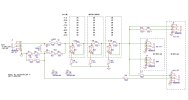
With the isolation transformer, I don't know how high you can make the resistors, particularly the 200Ohm, before it might start changing the tone due not to the amp and M2 but due to the way the resistors interact with the inductive reactance of the transformer.

But for the amp and the M2, if the 200 Ohm is found to be high enough that it has a negligible effect, there's not much to be gained by going higher. My simple run tested what I think will be the most sensitive condition , and the effect was very small. So it seems ok as it is. You can experiment though.

Your ohms readings look fine, all within 10% of 8 Ohms. The design is optimised for consistent tone and consistent attenuation steps, and also consistent output ohms (very important for tone!). The ohms work out best in the -7dB stages, but the -3.5dB and -14dB ones have to be allowed to vary a bit, in order for them to work as simple two-part stages. But that's ok because the amp never sees them directly. They are hidden behind Stage1, which keeps the ohms seen by the amp consistent enough.

For M4, Stage 1 can be switched to -3.5 so it has less effect of hiding whats downstream. So the -14 Stage has another part so it can be more accurate, but with a bit more complexity.

The main reason for the resistance tests is that it's a simple check that everything is wired up right, ahead of connecting an amp. If the ohms are all in the right range then it's safe to test.
 

Ben888

New Member
Joined
Feb 15, 2023
Messages
11
Reaction score
6
Great, thanks @JohnH

I did the resistance test before the first plug in and thought it would be okay being close. Thank you for your explanation, it’s a fascinating design and makes perfect sense. Thanks for confirming my numbers are normal.

Interesting about how the resistors could interact with the transformers inductance. It sounds like a balancing act with values, which may have been tested or calculated by Jensen already but id like to experiment. As you say, may not be worth it other than my own inquisitiveness as I’m not using a sensitive AC30 type amp but interesting none the less. I’ll try and find some information to research transformer inductance interactions!

Thanks for your support and so graciously sharing your knowledge and design.
 

JohnH

Well-Known Member
Joined
May 31, 2008
Messages
6,143
Reaction score
5,019
Location
Wilton NSW
As a comparison, here's a version of Suhr's reactive load (not a Suhr drawing though), with a transformer-isolated line-out. It seems to be set up for a much higher impedance, but maybe the transformer is quite different:

SuhrReactiveLoad1.JPG.jpg
 

jfromel

Member
Joined
Nov 21, 2020
Messages
46
Reaction score
33
My shopmate Simon turned me on to this thread and is making a 16 ohm version with big resistors for his rig this weekend. If we like it I'm going to make some SMD prototypes up. I have tried to make a lot of different attenuators over the years and for various reasons never made it a project. The thought of wiring up huge chassis mount resistors for production by hand doesn't float my boat. I saw more than a few comments from people wanting one already built so.....

I think I'm going to name the prototype "Will It Melt?". It's a 50w+ M2 8 ohm in, all 4 outs, no line out. Adding options (different builds) would be easy with change in resistors/daughter bords. This build will have 35w SMD resistors, the PCB is designed to act as a heat sink/double sided with thermal via's, 2 oz copper and the edges are bare metal to contact the chassis slot. All traces are 2oz copper 2.56mm wide. The coil size is the Dayton Audio 18ga. Thinking about getting a coil winder, design my own and fit in a shorter enclosure. Circuit is 100% isolated from the chassis. My guess is this config will work for 80% of amps out there.

I was trying to make this build as stupid simple as possible and this can be all robot made except for 2 solder points for the coil. 8 holes to drill on the end caps with no added air cooling. Should be easy to hand solder as these SMD resistors are massive. I am hoping no vent holes will be necessary and it will sit at a comfortably warm 75c (warm mug of coffee) when pushed. One can hope. but if I need to design venting system it's not the end of the world, just more drilling/cutting.

Thoughts? Would love to hear what @JohnH thinks (design, IP/licensing, Open source? yada, yada if I put this into production?). If I make a couple up does anyone want to do a field test and try to make it melt if Simon or I can't get the magic smoke to leave?Simple Annenuator SMD.jpg
 

Attachments

  • Attenuator cross section.jpg
    Attenuator cross section.jpg
    183.1 KB · Views: 22
  • Attenuator whole.jpg
    Attenuator whole.jpg
    253.8 KB · Views: 32
  • SCH_samto+_2024-03-15.pdf
    231 KB · Views: 10
  • Simple Anntenuator Schematic.jpg
    Simple Anntenuator Schematic.jpg
    254.2 KB · Views: 34

Ben888

New Member
Joined
Feb 15, 2023
Messages
11
Reaction score
6
That’s interesting. Yes it’s a 10k:10k transformer rather than the 600:600 Jensen. I wonder how that changes things..

There’s a useful resource here that has lots of various schematics for line out, line in and di box designs for Jensen’s various audio isolation transformers.


JohnH

Well-Known Member
Joined
May 31, 2008
Messages
6,143
Reaction score
5,019
Location
Wilton NSW
hi @Ben888 , that's a huge range of Jensen options! It looks like any version of output level and impedance is possible. What do you think would be the most useful general spec for a lineout circuit? We have plenty of output available from any amp, just need to bring it down appropriately.
 

Ben888

New Member
Joined
Feb 15, 2023
Messages
11
Reaction score
6
Hi @JohnH
Yes, there is a large selection of options for all occasions!
I’d say a useful spec for line out would be the industry professional standard 4db (1.23v) output and for that to be isolated.

Output impedance seems to be less standardised. 600 ohms output impedance was adopted from the telecom industry for impedance matching to prevent high frequency losses due to cable capacitance and reflections on long cables.

For studio use, impedance matching doesn’t work as well. 600 ohm into 600 ohm would be fine, but if your line out fed two 600 ohm inputs, the signal strength would be halved. Thus studio equipment used low output to high input impedance, so that signal strength is unaffected so much as to be irrelevant. Some references say a 1:10 ratio but standards vary. 600 ohm is still often used as an output impedance and can be as low as 100 ohms. For input, often 10k or more.

As you say, we have plenty hot enough speaker output to work from. I suppose the challenges are, what power amp are we designing for, as this affects the choice of voltage divider. And then as previously discussed, the load that voltage divider shows the amp.

I plan to put a temporary switch inline with my line out circuit to see if I can hear any attenuation of high frequencies with the circuit switched in/out.

I could also repeat that with my modded Laney LC15, which I could easily switch out the feedback loop to make it more sensitive like an AC15/30 type design.
 
Last edited:

jfromel

Member
Joined
Nov 21, 2020
Messages
46
Reaction score
33
Still waiting on a few parts, so far looking good..... It took me about 20 minutes to solder all the components on the board by hand.

- The side rails fit tightly in the slot.
- SMD parts were very easy to solder but it took some extra time to get the solder to flow on the heat sink pads. Hope that's a good omen!
- still waiting on coil, switches and one more resistor then, Testing Testing
- started prototyping a 3d printed enclosure for the full DIY experience.
att sm.jpg
 

Mark Baker

New Member
Joined
May 26, 2020
Messages
27
Reaction score
17
I had previously installed a MV in my SV20H with the help of a generous member on this forum. I just built the basic version of this attenuator and it is by far better suited down to the level I play in the house. Surprisingly, the best setting for me with this amp for volume and tone was on the 5w mode with the 3.5 and 7db switches on. Thank you to JohnH and all that contributed to this thread. I don't believe it. I just checked the MV thread from 2020 to see if it was JohnH that had helped me with it. It wasn't JohnH that helped me with the MV, but he did post on that thread suggesting to try this attenuator. I could have had this four years ago if I had listened to him then. SMH.
 
Last edited:

stickyfinger

Well-Known Member
Joined
Nov 11, 2010
Messages
1,164
Reaction score
696
Still waiting on a few parts, so far looking good..... It took me about 20 minutes to solder all the components on the board by hand.

- The side rails fit tightly in the slot.
- SMD parts were very easy to solder but it took some extra time to get the solder to flow on the heat sink pads. Hope that's a good omen!
- still waiting on coil, switches and one more resistor then, Testing Testing
- started prototyping a 3d printed enclosure for the full DIY experience.
View attachment 148935
That PCB and components can handle a dimed 50 watt Marshall? Personally I dont think I like the idea of that design.
 

JohnH

Well-Known Member
Joined
May 31, 2008
Messages
6,143
Reaction score
5,019
Location
Wilton NSW
Let's see, I'm watching too. It will need to be fully heat tested for power in vs component temperature. It's very interesting.
 

jfromel

Member
Joined
Nov 21, 2020
Messages
46
Reaction score
33
That PCB and components can handle a dimed 50 watt Marshall? Personally I dont think I like the idea of that design.
The components can handle it if the design is properly implemented. If it melts I don't think I will like the idea of the design either :) I'll post an update when the rest of the parts are in and it's been through a round or two of ROCK.

I had two EE friends in different fields who know way more about PCB design than me review it and thought it looked promising. In order to handle a fully dimed 50w the dissipation needs to be better than 75% (60c/140f) and may need some additional thermal management (vent, fan, additional sink's, etc) to keep the derating better than the target 60c.
 

jfromel

Member
Joined
Nov 21, 2020
Messages
46
Reaction score
33
Did some initial testing today with the lid on.

Test one - Cranked Blues Jr for 20 minutes
Result; Chassis never went above ambient (18c).

Test two - Cranked JTM45 w/ KT88's biased warm into single 8ohm C-Rex.
Result; quickly warmed up to 40c, after 20 minutes 60c, after 25 minutes 65c and shut it down. Tone remained consistent as temp of the chassis rose.

Keeping the chassis no hotter than a warm cup of cocoa (45-50c) should be possible with additional thermal management.

This thing sounds amazing!!!!! Feeling confident I can manage the heat dissipation.
 

Attachments

  • Attenuator proto.jpg
    Attenuator proto.jpg
    163.5 KB · Views: 19

JohnH

Well-Known Member
Joined
May 31, 2008
Messages
6,143
Reaction score
5,019
Location
Wilton NSW
Sounds promising! I'd really like to know temperatures right on the R1 resistora, do you have a way of checking that? I glad it sounds good!
 

jfromel

Member
Joined
Nov 21, 2020
Messages
46
Reaction score
33
R1 in this design is 4 35w 15ohm resistors in series/parallel. I can put sensors on them and run the leads out the front panel with the lid on.
 

JohnH

Well-Known Member
Joined
May 31, 2008
Messages
6,143
Reaction score
5,019
Location
Wilton NSW
Hi @jfromel

Yes I think that would be good, then we'd know.

You could try with the amp as power siurce but also, try with a known dc input instead of an amp. In that test, you can keep the input voltage low enough (eg 9V) that you can let it run for a long time and really let it reach a steady state. We'd know exactly what power is going in from P = V^2 / R. R is the measured input ohms.

Then, if the test is with say 10W, we can multiply up the expected temperature rise to estimate at 50W, or 75W etc. (that way of estimating for higher power will be slightly conservative)

It's a very simple data point, and a good comparison to the amp test which, although more real, has a somewhat unknown power . And also with this lower dc test, there's no risk to amp or attenuator. I use a 9V 2A wall wart for these tests, and an 8ohm attenuator draws about 1A from it.

Is something like that feasible for you?
 

jfromel

Member
Joined
Nov 21, 2020
Messages
46
Reaction score
33
Hi @jfromel

Yes I think that would be good, then we'd know.

You could try with the amp as power siurce but also, try with a known dc input instead of an amp. In that test, you can keep the input voltage low enough (eg 9V) that you can let it run for a long time and really let it reach a steady state. We'd know exactly what power is going in from P = V^2 / R. R is the measured input ohms.

Then, if the test is with say 10W, we can multiply up the expected temperature rise to estimate at 50W, or 75W etc. (that way of estimating for higher power will be slightly conservative)

It's a very simple data point, and a good comparison to the amp test which, although more real, has a somewhat unknown power . And also with this lower dc test, there's no risk to amp or attenuator. I use a 9V 2A wall wart for these tests, and an 8ohm attenuator draws about 1A from it.

Is something like that feasible for you?
That's super easy to do, I have a 3amp variable DC PS that can output between 5-50vdc. I have some more tiny heat sinks on the way. When you say long time are you talking hours, days?
 

JohnH

Well-Known Member
Joined
May 31, 2008
Messages
6,143
Reaction score
5,019
Location
Wilton NSW
hi @jfromel, ok great and that will be very scientific.

How long to run the test for is dependent on how quickly it heats. On my builds, it gets there close enough within about an hour, but in theory the last part is a very slow exponential convergence. This smd version may heat quicker though.
 

jfromel

Member
Joined
Nov 21, 2020
Messages
46
Reaction score
33
@JohnH Thanks so much for your help with the testing of this.

Sound wise, amazing. Simon thinks it sounds better than his 16ohm version with big resistors and possible factors may be shortened lead length and using 1% vs 5% resistors.

In Initial testing with no fans and no venting it was able to handle 20 watts without blinking, after that it started heating up.

I made a 3d printed lid to act as a vent, added tiny heat sinks to the resistors, drilled vent holes in the PCB, and tested as follows (this was with the lid off so I could directly measure the temp on R1).
Ambient Temp 20c
Time - Hours1.002.002.503.003.5044.55
VDC in9.0010.0011.0012.0013.0014.0015.0016.00
Resistance Ohms8.308.308.308.308.308.308.308.30
POWER - Watts9.7612.0514.5817.3520.3623.6127.1130.84
Current - Amps1.081.201.331.451.571.691.811.93
R1 Temp - C40.0045.0050.0057.0062.0067.0074.0087.00
Chassis Temp - C36.0038.0042.0045.0051.0052.0054.0064.00

When the test got to 30 watts the chassis was too hot to handle. Added 2 blower fans. This test is with the lid on (no R1 readings). I couldn't get past 40 watts because the power supply I was testing with didn't have enough current.
w/ fans
Time - Hours0.511.522.3
VDC in15.0016.0017.0018.0019.00
Resistance Ohms8.308.308.308.308.30
POWER - Watts27.1130.8434.8239.0443.49
Current - Amps1.811.932.052.172.29
R1 Temp - C
Chassis Temp - C44.0048.0053.0053.0055.00

Next step is to get a power supply that will handle the current to bench test at continuous wattage. Based on the charts above I am hoping that at 21VDC (53 watts) the chassis will stabilize at 60c.

I added some high range stick on thermometers (30c-60c) for visual reference only, I used real test equipment to gather data.

I am pretty happy how it turned out and now thinking about how to improve it.
 

Attachments

  • IMG_1997.jpg
    IMG_1997.jpg
    685.6 KB · Views: 26
  • IMG_1995.jpg
    IMG_1995.jpg
    791.2 KB · Views: 27
Top