DIY Build: Robinette 2Watt JCM800 EF80 with mods

  • Thread starter NickKUK
  • Start date
  • This site may earn a commission from merchant affiliate links like Ebay, Amazon, and others.

NickKUK

Active Member
Joined
Apr 5, 2024
Messages
139
Reaction score
122
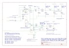
I'm also looking at options for clipping too.

DiodeGenCharacteristics1.jpg
Source: https://en.wikipedia.org/wiki/1N4148_signal_diode

This gives an interesting, empirical and objective view on diodes. I'm also looking at the options for running BJT based clipping (tying the based to either collector or emitter turns the BJT into a diode - this is the highlighted point with CB-connected) but it requires a little more design.

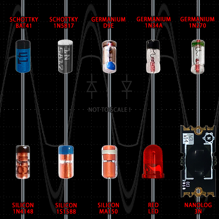
I also came across this which has a nice summary of pedal based distortion using the respective diodes:

What is interesting is the germanium diode has a non-linear response whereas the silicon and others have much more of a linear response - as you can see in the graph above where the line bends denoting non-linearity, vs the straight line showing more linear response. So I would expect the germanium diodes to sound different at different amplitude of string vibration and, oddly, this indicates that there's more clipping/compression in the centre of the waveform with less outside.
A shallow line means there's a slower distortion. This is why you have an aggressive Schottky sound (steep), vs the something like the 1N4148 that has a shallow line that allows it to be used in the Marshall blues breaker pedal or BOSS DS1 etc to get that clarity but even break up.

Additionally this page also does the same, a survey of diodes: https://therepaircafe.wordpress.com/2019/10/24/forward-voltage-of-various-diodes/
 
Last edited:

NickKUK

Active Member
Joined
Apr 5, 2024
Messages
139
Reaction score
122
So I'be been job hunting so this has taken a backseat but with Oasis making a comeback, I thought I'd try some dirty - edge of breakup sounds on the little amp.

It sounds more muted on the phone, perhaps due to angle but where I'm sat there's still a decent clarity to it.


NickKUK

Active Member
Joined
Apr 5, 2024
Messages
139
Reaction score
122
So I've ordered the bits to at least get it a 'complete' state:

* Royal Blue tolex, with blues breaker re-issue grill cover, gold and white piping
* gold mesh
* two dogbone handles
* t-nuts and bolts
* 500V caps to replace the existing 450V caps
* switch for tube/solid state (with and additional 47uF in solid state mode).
* a 10% attenuator (simple resistive) as a second jack
* jack insulators so I can remove the electrician tape acting as a insulator
* switches for adding bypass of the 43% voltage divider I have after the master volume, for bypassing the tone stack
* corrective presence pot and resistor values
* bias pots for the output stage.

So this should look good, the 10% attenuator should allow me to crank up the volume without it being ear splitting.
 

NickKUK

Active Member
Joined
Apr 5, 2024
Messages
139
Reaction score
122
Whilst the neighbours are away..

Here the amp is playing loud - just to show what the little 2W amp will do volume (sorry I'm a crap player at best and anxiety of recording makes it worse). One of the things I want todo is get back into proper playing so next year I'm likely to start with lessons.

The amp itself has a hard 43% signal attenuator after the master volume but before the LTP, this means the pre-stages need to be cranked to get to trigger output saturation. The bypass switch will allow this to be maxed out with less preamp gain.

1. Low Gain input
* bridge pickup (~1.5Vpp)
* neck pickup (~2.5Vpp)

2. High gain input
* neck pickup
* bridge picklup


The iPhone doesn't get the same bass or treble but hope you get the idea.
 

NickKUK

Active Member
Joined
Apr 5, 2024
Messages
139
Reaction score
122
Bits arrived :D

I now have a long list of things that need completing for the cab and amp..

IMG_3607.jpg


I've also moved my amp schematic to kicad as it's clearer in sheets rather than ltspice. I've attached the current versions (missing a couple of bits but it's to give an idea.
 

Attachments

  • pow.jpg
    pow.jpg
    582 KB · Views: 6
  • pre-2.jpg
    pre-2.jpg
    841 KB · Views: 7
  • ps-3.jpeg
    ps-3.jpeg
    837.4 KB · Views: 4

NickKUK

Active Member
Joined
Apr 5, 2024
Messages
139
Reaction score
122
So the next phase of amp cab is going ahead this weekend.

Currently just glueing in the recycled pine table structs to support the baffle. It's measured up so that with the baffle, a front frame, tolex and grill cloth, the front will be 5mm back from the edges of the front.

IMG_3618.jpg

Once this has set in the next couple of hours, I'll add a vent, fit handle and support plus wheel screw patches and route the piping spots along the top and bottom.

I also have to then glue on the front baffle frame, embedding the tnuts for the front baffle. I have to wait for some clamps to become free!

The amp is partially disassembled, with desoldered components, new holes drilled for firmware and now needs resoldering/assembly.

The idea is to have a clean cab ready for tolexing over the weekend.
 

NickKUK

Active Member
Joined
Apr 5, 2024
Messages
139
Reaction score
122
Update in the cab thread, but the amp and cab are 'complete' pending further tinkering.

The amp now has:
* switchable 240/230V primary
* tube/solid state rectification switchable
* post-MV pre-LTP attenuation switchable bypass
* switchable hard clipping using symmetric and asymmetrical diodes (like of like boss distortion vs overdrive).


NickKUK

Active Member
Joined
Apr 5, 2024
Messages
139
Reaction score
122
Playing around with clean-edge-of breakup and bluesy notes (a YouTube mangled version of Sunshine of your love):
 
Last edited:

NickKUK

Active Member
Joined
Apr 5, 2024
Messages
139
Reaction score
122
So I've come up with this dual switch approach to enable switching between JCM800 cascaded first two stages and JTM45 differential amplifier first two stages using the same v1 tube.

It uses one 3 pole switch to switch the power:
* switches between JCM's 100K and JTM's 180K anode resistance
* switches cathode configuration - either a JCM's 2k7+0.68uF and 10K cold clipper, OR, JTMs joined cathode with 820R+250uF (it leaves the 0.68uF in the loop). An enhancement could remove that 0.68uF by putting it on SW?A port 1 thus it would be switched out completely.

The second 3 pole switch then switches the signal path:
* switches to route the signal of v1a via the audio jack to v1b in standard cascade format, OR, leaves the two inputs into separate v1a/b but routes the output of v1a/b via to mixing pots to the output signal path
* to minimise the number of switches in the signal path, and not have the mixing pots cause a route to ground and thus acting as a volume on the JCM setting, the ground for the pots are severed by the remaining switch pole, leaving the pots floating with the signal.

In the diagram below I used a 2 pole symbol but duplicated the B unit of each switch to provide the 3rd pole. I know Carling provide a 3 pole switch that would do the job of power switching, the signal switch can be left to a smaller switch.

Screenshot 2024-09-20 at 16.13.06.png
 
Top