• We are looking to make improvements to the Classifieds! Help us determine what improvements we can make by filling out this classifieds survey. Your feedback is very appreciated and helpful!

    Take survey

Simple Attenuators - Design And Testing

  • Thread starter JohnH
  • Start date
  • This site may earn a commission from merchant affiliate links like Ebay, Amazon, and others.

6StringStewie

Well-Known Member
Joined
Jun 10, 2017
Messages
317
Reaction score
282
Location
Springfield, Ohio
@JohnH

For a 100W amp, Build M R1 is spec'd at 200W. I found a couple of inductors with a value of 200W RMS. Those should work since the attenuator isn't expected to see all 200W, correct?

Are the L1 and L2 values the same for a 100W amp as a 50W amp? Have you run any Spice models with a 100W amp? (I thought I read earlier that L2 should optimally be 2x L1 for a 100W amp, but I haven't been able to find that post. Going to start a re-read of the thread this week.)
 

JohnH

Well-Known Member
Joined
May 31, 2008
Messages
6,156
Reaction score
5,062
Location
Wilton NSW
Hi @6StringStewie
The required inductance values of coils and also the Ohms values of the resistors aren't affected by the amp power, they only relate with which speaker ohms tap you use on the amp. The inductors don't absorb much power if they are thick enough wire, nearly all of ths power is soaked up by resistors. What they need is thick enough wire to give low resistance. I'm using 18 Gage wire in my coils, which is definately fine with a 50W 8 ohm build. I think that will also be ok with a 16ohm build up to 100W. otherwise, go a greater thickness., say 16 Gage.

let's ask @matttornado what wire Gage are in his, for his 16Ohm build for a 100W Plexi, and if the coils are heating up much beyond having hot resistors nearby.
 

Marvelicious

New Member
Joined
Dec 1, 2019
Messages
13
Reaction score
1
Forgive me if this has been covered... I searched a little bit and there has been some discussion of other Lpad based designs, but didn't really find something that really spoke to it. It might be here, and I might be blind...

Anyhow, I've played around with Lpads and they tend to sound like a wet blanket on the speaker, but that is how a purely resistive load tend to sound. The key to this is the reactive stage 1. I'm wondering if you've tried feeding stage one into an Lpad for further reduction? The following stages are just resistive stages anyway, and theoretically shouldn't sound different than an Lpad...

Of course, as the saying goes: the difference between theory and practice is that in theory there is no difference.
 

JohnH

Well-Known Member
Joined
May 31, 2008
Messages
6,156
Reaction score
5,062
Location
Wilton NSW
Hi @Marvelicious , Thanks for joining this thread.

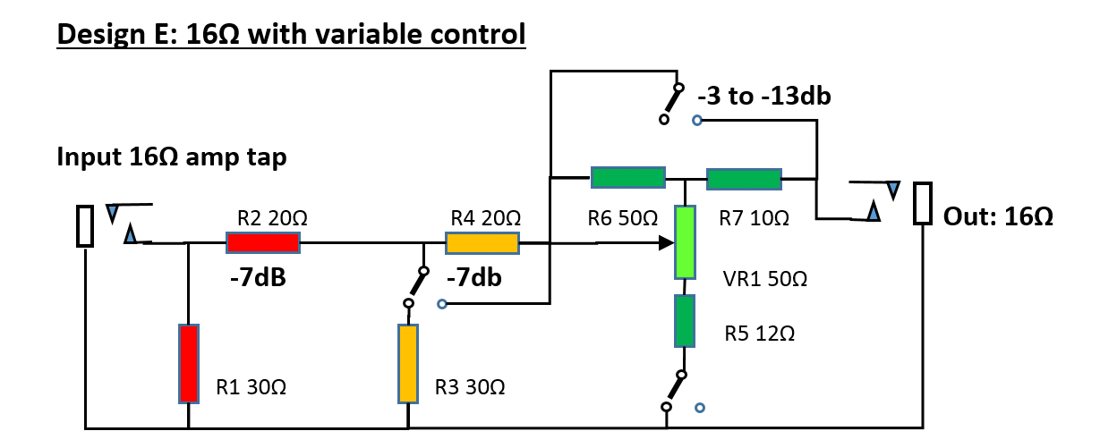
What I realized is that the fundamental reason why L-pads sound like wet blankets is not because they are non-reactive, it's because they are not the best way to make a resistive attenuator. The key thing is that as you turn down, they show the speaker a very low impedance which damps down it's treble and bass resonant response. The resistive stages that I use keep the output resistance consistent and high, based in a real tube amp response. So a normal L-pad even after a reactive Stage 1 would still sound dull.

Doing the attenuation in switched stages means that each one can be tuned to get this correct. But I did work out a design for a final stage using a pot. Almost as consistent in the analysis, but never tried in practice.


That's from July 2018, before I had the reactive module worked out, but it should work ok as a final stage, after a reactive Stage 1.

In my designs, the basic frequency response at the output is controlled by resistor choices. The reactive Stage then adds reactive response at the input, which corrects the dynamics of the amp.
 

Marvelicious

New Member
Joined
Dec 1, 2019
Messages
13
Reaction score
1
Interesting... I'll admit, I've never opened up an Lpad to see how they actually do their job. I hadn't considered the "back side" of the circuit.

In truth, the main reason for my interest in using an Lpad was to avoid the individual binary switches for packaging purposes. I originally considered a big multi-deck rotary switch, but the price for a switch that will handle the current is a bit prohibitive.
 

JohnH

Well-Known Member
Joined
May 31, 2008
Messages
6,156
Reaction score
5,062
Location
Wilton NSW
That's where Gene and I got to too. Capable toggle or slide switches are easily obtained, but rotaries are either expensive, unavailable or under-specced. Three toggles will give you 8 settings and a simple clean wire-up. But a 3-pole 8-way rotary for several amps is not something that can be easily found and the build is a rats nest.

The design is set up for the amateur builder, and it's best if you love binary math too, whereby each stage is double the previous in terms of db's. Actually, it's easy to use once you get the feel for the volume influence of each switch, and the 3.5db steps are really quite small.
 
Last edited:

Marvelicious

New Member
Joined
Dec 1, 2019
Messages
13
Reaction score
1
I actually sketched it up with a 5P10T rotary with a bypass setting, 7 - 31.5db attentuation (I omitted a setting for non reactive 3.5db only) and a full mute setting with an additional 8 ohm dummy resistor. I managed to find a 5a rated switch for $70 - which isn't bad considering, and I'm tempted... there's something appealing about being able to simply turn the knob down. The switch is physically pretty big, so it wouldn't be the tightest rats nest I've wired.
 

JohnH

Well-Known Member
Joined
May 31, 2008
Messages
6,156
Reaction score
5,062
Location
Wilton NSW
Sounds like a project!

I think if it was mine, I'd do the bypass as a separate toggle, then the whole rotary is working at reduced current and you can better control transient issues as you switch to bypass. Also, break before make or make before break is relevant for the rotary. Probably want make before break.
 

Marvelicious

New Member
Joined
Dec 1, 2019
Messages
13
Reaction score
1
Yeah, the whole live switching issue complicates the hell out of it. Pretty much has to be make before break to keep it from briefly being an open circuit. The trouble is that when in between positions you wind up with some odd combo of the main circuit being paralleled with whatever odd ground leg (R3, R5, R7) it is switching from or to while the corresponding inline resistor is shorted. If that makes any sense... you obviously understand the issue even if I'm not phrasing it well.

Unfortunately, having to bypass to switch between setting pretty much kills the cool factor of the rotary switch as far as I'm concerned and I can buy a lot of toggle switches for $70. At the moment, I don't know whether those switches I found at that price are make before break or otherwise. The choice may make itself for me...
 

JohnH

Well-Known Member
Joined
May 31, 2008
Messages
6,156
Reaction score
5,062
Location
Wilton NSW
I'd expect that if the bypass switch was separate, then you'd be ok to dial the rotary freely without operating the bypass. Even if there was an instant where all make before break contacts were connected, I don't think the amp sees less than about 7 Ohm for the 8 Ohm version.
 
Last edited:

Marvelicious

New Member
Joined
Dec 1, 2019
Messages
13
Reaction score
1
Oh, that would definitely work, it just makes it not worth the money for the expensive switch. The "cool factor" of just reaching up and turning the knob down is totally blown if you have to switch it into bypass mode first, then pick your setting, then kick it back on.

I'll probably build it as-designed and try it out first. If I like it enough, maybe I'll revisit the rotary, or maybe I'll decide I don't care...
 

JohnH

Well-Known Member
Joined
May 31, 2008
Messages
6,156
Reaction score
5,062
Location
Wilton NSW
Good luck whichever you decide. What sort of amps would you use it for?

I built all the bells and whistles into my current build, just so I could test them out. But when I do another, it will probably be more stripped back, with no bypass switch and no -3.5db first setting. Omitting these takes significant pressure off the switching and simplifies the build. There are good work-arounds for both these. If a small first step is needed, the box can be wired in parallel as a load, to get -3db using a lower amp tap. And if I need fully loud for a party, I just don't use the attenuator.
 

Marvelicious

New Member
Joined
Dec 1, 2019
Messages
13
Reaction score
1
What amps... Well... There's the Ampeg V2, there's the Marshall 3203, there's that half built Carmen Ghia clone, and I have a JTM45 based idea sort of brewing in my head as well... Plus a pile of different combos that I could technically use it with.

The whole thing started with the intent to make a dummy load for testing purposes, which led me to doing a bit of reading on reactive loads, which led me to attenuators...
 

JohnH

Well-Known Member
Joined
May 31, 2008
Messages
6,156
Reaction score
5,062
Location
Wilton NSW
The things I was wondering about was what power and what amp tap 8 or 16 ohms, would you build for? Would all your amp ootions be able to work with one choice? The designs so far are each dedicated to either 8 or 16 at the amp, and then at the output you can use either 8 or 16 on either version, or even 4 Ohms.

What we don't have so far is switchable input impedance. Commercial units that claim to offer this are often doing it just by putting a parallel resistor at the front, which works safely but kills off at least half of the effect of the reactive impedance for the amp.

If you need an 8/16 input option, we could work out a reactive version that would work properly, although it would reduce by a further 3db when engaged.
 

Marvelicious

New Member
Joined
Dec 1, 2019
Messages
13
Reaction score
1
Nope, just going 8 ohm for the time being. Most of my stuff is switchable. My main use is really for testing purposes... being able to make sure there aren't any elusive issues at high volume without fracturing my ear drums. I have kind of a thing with small vintage combos, so I have plenty of things to play when I want low volume.
 

bodhi

New Member
Joined
Dec 6, 2019
Messages
6
Reaction score
0
First of all, thanks for such an amazing resource!

I recently purchased the parts for a build, with the idea to use a rotary switch to set the attenuation level. I bought a fairly cheap ceramic rotary switch that you can find on ebay, but based on the recent messages I'm starting to wonder what kind of current rating would be required for a switch to be safe to use in the attenuator? Unfortunately I'm more of a paint-by-numbers person regarding most of the electronics behind these matters and haven't yet worked through the math (or found the proper references) to figure out what kind of voltages and current are passed between an output transformer and a speaker.
 

JohnH

Well-Known Member
Joined
May 31, 2008
Messages
6,156
Reaction score
5,062
Location
Wilton NSW
Hi @bodhi - thanks for that queston and Im glad you asked it before building!

The current through the switch will depend on the power of the amp, the ohms rating you are building to and whether or not the rotary is involved in creating a full bypass, or are you having a separate bypass switch (or no bypass)?

in terms of current and resistance, Power = Current^2xR, or Current = (Power/R)^0.5

Examples:

100W amp running at 8Ohms, with all of that going through the switch. Current = (100/8)^0.5
= 3.5A

50W amp running at 8 ohms, Current = 2.5A

50W amp running at 16Ohms, Current = 1.8A

10W amp running at 8 Ohms, Current = 1.1A

Now, if the switch in question is only after Stage 1, then it doesn't need to handle all of the power. With our design, all of the current valuess above would be reduced x 0.45.

Once you know all that, then to specify a switch, you then need at least an extra x2 factor on current handing.

So for those basic rotary switches, they are unlikely to be adequate if you want to crank your amp, unless it is very low Watts.

BTW: Switch specs often give you current rating for dc, and ac at 125V or 250V. If you have those specs, the 125V ac will be the highest value, and we can use that. The voltages we use are much lower.
 
Last edited:

bodhi

New Member
Joined
Dec 6, 2019
Messages
6
Reaction score
0
Thanks for the swift reply! Similarly to @Marvelicious I kind of thought to have it with the bypass included, just to be able to have a simple switch to turn it down, but might need to reconsider now with the proper calculations. After a while I ended up finding the same formula at the 18 watt forum.

I'm still at a bit of a loss regarding the expected voltage swing between the OT and the speaker though, since unless I'm mistaken this should allow for essentially a larger current rating than what the nominal x ampere @ 125 or 250 VAC that can be found. Typical OT impedance switches seem to be rated for 6A @ 125VAC, which is probably a safe value for the 100W Marshalls they might be used with, but I've seen some low wattage (the one I'm thinking of is 5w) with a common switchcraft slide switch, which seems to be rated at 3A @ 125VAC. Based on the calculations though, this seems to be easily within safe margins with the provided impedance settings.

It seems like the rating for similar rotary switches to what I've found are only 350mA or up to 0.5A, so it seems they're not really usable at all for this purpose. Not a lot of the common rotary switches seem to have a rating in the range required, or then there's not enough steps to get the full range available.

As for background, I'm probably going to start by building an external box to connect to the amps I have available, but I was considering integrating something like this into a couple of amp kit builds in the 18-25W range if it all seems to work out. I live in a fairly badly isolated apartment and need something like this to be able to play without the computer and headphones...
 

Gene Ballzz

Well-Known Member
Joined
Feb 19, 2013
Messages
4,697
Reaction score
6,521
Location
Las Vegas, NV
@bodhi

First, welcome to the forum and one of the most enlightening and potentially liberating threads here. Constructed and used properly, these attenuator designs will allow you to use almost any amp, cranked well into its "Sweet Spot" at any chosen volume/sound pressure level, while retaining tone and tactile response!

:welcome:
Next, I feel obligated to ask: If "bodhi" is your first name, is your last name "sattva?" :naughty:


Just Curious?
Gene
 

JohnH

Well-Known Member
Joined
May 31, 2008
Messages
6,156
Reaction score
5,062
Location
Wilton NSW
Gene and I also tried to think through how to use a rotary, and where they might come from. but the numbers based on current vs switch positions vs size vs $ just didn't seem to stack up! And actually, once you get used to the 'binary' switching in either equal or x2 steps, it just works simply. You find an appropriate setting and leave it there and get on with playing the guitar.

Voltage swings coming out of amps:

Power = V^2/R so Voltage = (Power x R)^0.5
for a 100W amp into 16 Ohms,
V= 40V
if the Power is RMS, then there is a further x1.41 factor to get to the peak voltage. I'm not sure whether switch voltage ratings are based on that or RMS

But I think that confirms how 125vac is a reasonable and safe voltage spec for deciding on switch current ratings. It doesn't tell us if at lower voltage, there may be a tad more current rating available. But it also is consistent with output switches being rated for 6A @ 125vac, though you'd be pushing up to the limit if cranking a 100W into 4 Ohms (=5A)

What could you do with a 0.5A rotary?:

ie, let's say you could accept a separate bypass switch, or none, what power amp could be handled?

I think I'd still want a minimum margin of say 1/1.5, so I'd let the current be 0.33A. By putting the rotary contacts only after Stage 1, then the current coming in from the amp could be 0.33/0.45 = 0.73A.
If I use a 16Ohm tap (to get more power with less current), I can deal with an amp power of
0.73^2 x 16 = 8.5W.

So maybe there is scope for using simple rotaries with the low-watt amps.
 

Latest posts


Top