• We are looking to make improvements to the Classifieds! Help us determine what improvements we can make by filling out this classifieds survey. Your feedback is very appreciated and helpful!

    Take survey

Simple Attenuators - Design And Testing

  • Thread starter JohnH
  • Start date
  • This site may earn a commission from merchant affiliate links like Ebay, Amazon, and others.

telesto

Member
Joined
Apr 29, 2020
Messages
67
Reaction score
8
Thanks John, I had actually just worked out roughly the T-attenuator values myself, and you are already on the Pi-Attenuator, LOL, you are like some calculator/Excel sheet Terminator I see ;)

Actually, back to the T-Attenuator, I was thinking to put a 7ohm first series, 1 ohm shunt, 17ohm second series. Does that look OK to you? I have to re-check later, wrapping up for the day now.
 

JohnH

Well-Known Member
Joined
May 31, 2008
Messages
6,157
Reaction score
5,062
Location
Wilton NSW
I plugged those in, 7, 1 and 17

It looks like that hits the 8 and 18 impedance targets and offers about -28 db attenuation.

But who ever heard of a 17ohm resistor? Or is it a pair of 33's in parallel?
 

telesto

Member
Joined
Apr 29, 2020
Messages
67
Reaction score
8
Thanks Terminator. I was just looking at "ideal" values, yea, didn't consult actual resistor values. Ok, -28dB is a few short of 33, but maybe still OK, I'll have to try it and see. 17ohm doesn't seem to be available for power resistors, but in the circuit, it will have way under 1 watt on it, so they will be small and cheap 2W resistors needed (ie: not big power resistors), so I can play around with resistors in series or parallel to come up with the needed value, shouldn't be a problem. The first series resistor will take the brunt of the power (~90%) I can get 6.8ohm, and the shunt will take about 10% I can get 1ohm, and the speaker and second series have almost nothing in terms of power. Actually, the second series resistor can vary widely and have almost no affect on the 8ohms that the amp should see. Only the "reverse" impedance (what the speaker sees) will be affected by that value. Actually, the speaker impedance wouldn't matter much either, eg. I can connect a 4,8 or 16ohm speaker, and the amp should still see about 8ohms, if I am correct.

Question: how far above/below the target of 18 ohms is still "acceptable"? And which is "worse"?.. to go above or below 18ohms? I saw with the L-pad that going too far below (eg. 1 ohm or less) is a very bad "tone-sucker". I would guess if the speaker is seeing something +/-10dB of the 18dB target it should still be OK in terms of acceptable tone?

PS- The idea of building a Stage 1 with inductor and adding a T-attenuator after is an interesting idea, I'll have to go into that one a little deeper maybe...
 
Last edited:

JohnH

Well-Known Member
Joined
May 31, 2008
Messages
6,157
Reaction score
5,062
Location
Wilton NSW
With the output impedance, going higher tends to relatively reduce mids and add highs and bass resonance, lowering it does the opposite, adding mids.cutting high treble etc

I found that a factor of two is very significant, but smaller variations, I dont know, it would be down to how it sounds with your amp and how you like it.

If you have some spare resistors around, you could try putting 20 ohms extra in series and then alternatively in parallel, with the speaker just using your current wire-up, just to explore.. Or for a smaller change, a larger parallel one or a smaller one in series
 
Last edited:

JohnH

Well-Known Member
Joined
May 31, 2008
Messages
6,157
Reaction score
5,062
Location
Wilton NSW
Well I noticed a big difference with putting a 16 ohm speaker into the 8 ohm attenuator, so the speaker is seeing half the impedance it expected. Not a terrible sound, but a significant change. It would be the same if an 8ohm speaker was seeing say 9 or 10 instead of 18 or 20 ohms
 

telesto

Member
Joined
Apr 29, 2020
Messages
67
Reaction score
8
Well I noticed a big difference with putting a 16 ohm speaker into the 8 ohm attenuator, so the speaker is seeing half the impedance it expected. Not a terrible sound, but a significant change. It would be the same if an 8ohm speaker was seeing say 9 or 10 instead of 18 or 20 ohms
Ah Ok, I got you now. You're saying to treat the "reverse" impedance (speaker looking at amp) the same as the "forward" impedance (amp looking at speaker)
 

telesto

Member
Joined
Apr 29, 2020
Messages
67
Reaction score
8
Hey, I tried the T-Attenuator, 7ohm series, 1 ohm shunt, 17ohm series, and liked the sound of it :) I was thinking to stick an inductor in there and see how it sounds. What if on the first series resistor (7ohm) I take two 14ohm resistors in parallel and stick a coil in between, like you did on the M2? Do you see any downside to that, or any better idea?
 

JohnH

Well-Known Member
Joined
May 31, 2008
Messages
6,157
Reaction score
5,062
Location
Wilton NSW
Hey, I tried the T-Attenuator, 7ohm series, 1 ohm shunt, 17ohm series, and liked the sound of it :) I was thinking to stick an inductor in there and see how it sounds. What if on the first series resistor (7ohm) I take two 14ohm resistors in parallel and stick a coil in between, like you did on the M2? Do you see any downside to that, or any better idea?

You can try but the result may be random and sound bad/not good/not quite right/something missing. Reactive Stage 1 needs to be very carefully balanced between inductor and resistors so the inductance is partly in series and partly in parallel with the later stages.
 

telesto

Member
Joined
Apr 29, 2020
Messages
67
Reaction score
8
Ok, how did you reach the conclusion about the inductor needing to be part series, part parallel? Did you base it on some theory/calculation? Spice sim? Or did you just simply experimented until you found something that worked good?
 

JohnH

Well-Known Member
Joined
May 31, 2008
Messages
6,157
Reaction score
5,062
Location
Wilton NSW
Spice sims are probably the quickest way to test these things, and see clearly what is happening. Having the Inductance in series or parallel can both show the amp a reasonable reactive imoedance, but all in series will reduce treble fed to the speaker, while all in parallel will tend to boost treble. Hence a combination works best, either two inductors as I'n M, or one inductor feeding via two resistors as in M2.
 
Last edited:

Boysenman

New Member
Joined
Jun 7, 2020
Messages
7
Reaction score
1
@JohnH

Sorry for not getting back sooner. You're really incredibly helpful regarding the 10" speaker design. I really appreciate it.

So, if I get you right, if I wanted the design the M3 attenuator, with regards to the small 10" speaker, I would only have to reduce L1 (in the M3 schematic) from 0.9mH to 0.6mH, while all the resistors stay the same? Would I need to make any changes to L2 or C1 as well in this case?

Also, I want to understand why Aiken has chosen the bass resonance with an impedance of around 80-100 ohm, while your schematics are placed lower if I'm not mistaken? An impedance of 50-60ohm is similar to that of the impedance plot of the alnico speaker, you simulated. I would assume that a small voice coil inductance, compared to a similar leak resistance, would have an equally lower bass resonance impedance? Of course, I could for all intend and purposes make a switch that selected 3 different notches of bass resonance amplitudes, and likewise, 3 different levels of treble attenuation by varying the leak resistance. Either way, it seems fairly easy to tweak afterwards. The coils and the capacitor are much more expensive to come by.

kind regards
Boysen
 
Last edited:

JohnH

Well-Known Member
Joined
May 31, 2008
Messages
6,157
Reaction score
5,062
Location
Wilton NSW
Hi @Boysenman

A bit about M2, M3 and the M3 resonance circuit:

On the pure load box designs, such as Aikens, designed to work with no speaker, then to get that resonance you have to have the big cap and the big coil. It's the same with the active or reamped attenuators such as most of the expensive ones including OX and Boss TAE etc.

But for our design, the need for it is far less compelling, in fact, no one has built it yet to my knowledge and no one has noticed any problem. In M and M2, we get that resonance directly and naturally by the interaction of the attenuator with the real speaker. This means that if you change to a different speaker, 10 or 12", or closed-open cab, the result adjusts with no changes to parts. The only difference is that at these very low frequencies, the amp doesn't see it. The result is probably a more solid and consistent bass, theoretically with less bass distortion if you pump those very low notes.

But does if make an audible difference at all? so far I'm thinking not, and I haven't ponied up the $100 extra in parts to build it.

But if you go back to my last set of clips on page 50, 23rd May, I was really trying to reveal some difference full volume to attenuated in these low frequencies. Ignore my playing, tone and recording quality, but just try to listen for any difference in the low bass. The recording was through a 2x12 open back combo, probably with a resonance at about 80hz, and I was playing in drop D with several notes around there. I can't hear any difference in the normalized clips. And I was pushing the amp to try to provoke some result

So I suggest not to go for the full M3 until youve tried it just based on M2. Also, to make the M3 resonance circuit ideal, it has to be matched to the true resonance of your own speaker and cab. If it doesn't, it's all fine, still works etc, but it's not doing what's intended and might as well omit it since it sounds fine without

Also, getting a very sharp bass resonance peak at the amp needs big cap and big inductor, so more cost, particularly with the 8 ohm design That might be where designs you've seen are less than the theory
 
Last edited:

telesto

Member
Joined
Apr 29, 2020
Messages
67
Reaction score
8
Regarding speaker size or type, I don't think that will have much difference in regards to an attenuator, if I am correct. John used the 12" Greenback as a reference, but could have been any other speaker and results should be the same, or very similar. But yea, good to verify by testing some other types just to be sure. I think you verified that in the previous page?

One other comment regarding speakers, be aware that 10" speakers usually have less efficiency than 12" speakers. Most 10" have a speaker efficiency of about 95dB and 12" are around 100dB. That's the reference amplification at 1 Watt. So if you switch from a 12" speaker to a 10" speaker, you will get some dB's of attenuation "built into the speaker". Just something to consider :)

celestion10.JPG
 

telesto

Member
Joined
Apr 29, 2020
Messages
67
Reaction score
8
Ok, I went an upped my game today and screwed the resistors to a board instead of leaving them loose. Wasn't really a good idea having them loose, as they would shift around and were in danger of shorting out (kids, don't try that at home!)

I stuck the inductor in as well, but was kind of disappointed, as I didn't really notice any difference with or without. I experimented with it on the T-attenuator, and same thing, no difference. Or maybe even better without it. I tried with two different amps, same thing. Is it a subtle difference? Have other people experimented with/without the inductor? I have a fixed 28dB attenuation, maybe the inductor is more noticeable at higher volumes? At the moment, I see no need for it, and will probably leave it out of my final build.

*edit*
ok, I went back to page 6-7 and see John also had the impression that the impact of the inductor was negligible. ..so then why leave it in?

*edit 2*
Putting the issue of tone aside for moment, would the inductor have any impact positive or negative on the amp itself? Meaning an amp is meant to interact with an inductive speaker load. If it sees just a fixed 8ohms without impedance swings, is that good, bad or doesn't matter, from the amp point of view?

IMG_20200617_164151.jpg


(Picture has inductor removed from the circuit. To put it in, I would take the wire on the left side of the top resistor connecting to the resistor below it, and connect it to the free inductor connection. The wire that looks like it's going into the screw holding the inductor is actually connected to the other inductor lead)
 
Last edited:

JohnH

Well-Known Member
Joined
May 31, 2008
Messages
6,157
Reaction score
5,062
Location
Wilton NSW
I think an amp is safe going into a purely resistive load. The inductor is a subtle difference, sometimes noticeable sometimes not, depends on the amp and how you play. It is most likely to be noticeable if the preamp is not distorting too much and the power amp is driving hard, and you are using a wide dynamic range in your playing, sometimes playing lightly, sometimes digging in, letting notes ring out etc. Check out page 9 where Gene first got his going. My own first impressions were before I had the values quite right.

Also, discovered much later, but the reactive circuit seems to be able to adapt to different amps much better. Its there to be seen in the analysis but hard to explain.
 

telesto

Member
Joined
Apr 29, 2020
Messages
67
Reaction score
8
Ok, I did some further A/B testing with/without the inductor, and yea, I can hear a little difference, but very little, almost negligible in my tests. Of course depending on amp, playing style, etc your mileage may vary. But in my opinion, it's not really needed.
 
Last edited:

JohnH

Well-Known Member
Joined
May 31, 2008
Messages
6,157
Reaction score
5,062
Location
Wilton NSW
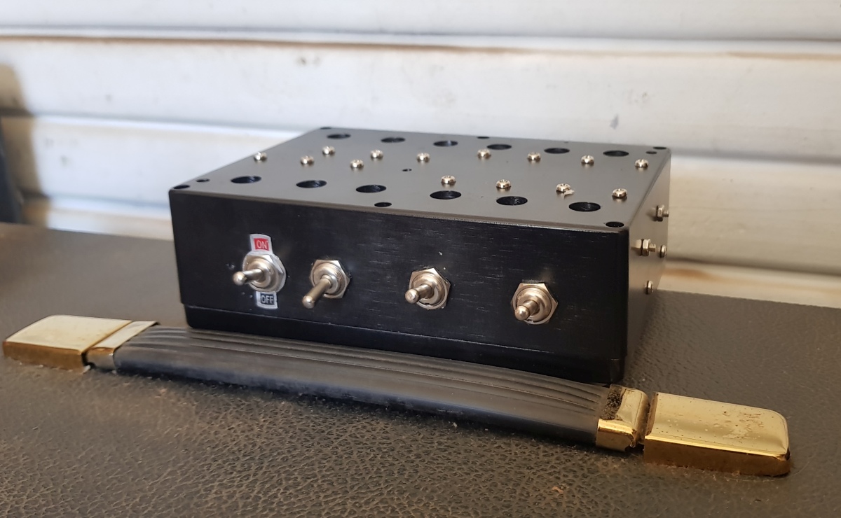
I still have a prototype resistive version, this one, from 2 years ago:

20200620_215115_resized.jpg

This has three stages of -7, -7 and-14 db so -28db max. I did some A/B comparison against my last build, Design M with the coils and -31db max:


The M is bigger and heavier, with several more features as well as reactive input. But the core resistive design is the same.

Running them both again with the VM, both set at -28db, the resistive design isn't bad at all, the tone is consistent and clear. But the reactive one is just a bit more lively, more present and responsive. The resisistive one has the tone, but its more constant, more like a good sim of an amp rather than the real deal.

Another thing I noticed is how the presence control on the amp is significantly more effective into the reactive input which makes sense since it is changing the amps output impedance at high frequencies as it varies NFB.

Its all quite small differences, it's not like one is a wet blanket and the other isnt. Each may have a place
 
Last edited:

Latest posts


Top