• We are looking to make improvements to the Classifieds! Help us determine what improvements we can make by filling out this classifieds survey. Your feedback is very appreciated and helpful!

    Take survey

Simple Attenuators - Design And Testing

  • Thread starter JohnH
  • Start date
  • This site may earn a commission from merchant affiliate links like Ebay, Amazon, and others.

telesto

Member
Joined
Apr 29, 2020
Messages
67
Reaction score
8
Hi John, one observation/comment regarding the inductor: I'm using amps with relatively low wattage, 10W and 20W amps respectively (Laney Cub 10 and Jet City 20H). I vaguely recall reading somewhere (Aiken?) that inductors have less effect on lower watt amps (?) Maybe this is the reason I'm not noticing much difference with/without the coil? You are doing your testing mostly with a 40W amp, is that correct?

Another remark, I'm using a 0.82mH 1mm thick Visaton coil in the M2 configuration. I also played around and tried a "split coil" formation (0.4mH with 22R series, and 0.6mH shunt) together with a T-attenuator, but the coils sounded saturated or distorted or something. I didn't really do any sim or math, I just sort of mimicked the original design Stage 1, but with different resistor values. Didn't work out well, but I was just playing around and experimenting.
 

JohnH

Well-Known Member
Joined
May 31, 2008
Messages
6,157
Reaction score
5,062
Location
Wilton NSW
Yes my main amp is a 50W Vintage Modern, though its apparently really in the high 30's of Watts in comparison to others.

I found the schematics for your amps online:
https://www.thegearpage.net/board/index.php?media/laney-cub-10-schematic.8667/full
https://usermanual.wiki/Document/JCA20HSchematic.1420896408

Looks like the Cub10 has 6V6 output valves and EL84s for the Jet City 20H? So different from the EL34s of most Marshalls, or the big-ass KT66s in my VM. Also, both amps have negative feedback loops? The Jet City looks like it offers you a presence control with it, with the Cub10 doesn't?

Both of these features, small tubes and negative feedback will affect the real output impedance of the amp. If it becomes relatively low due to the design, then this could explain why the inductance has little effect. It may corelate to Aikens comment too. What is good is that even with these two very different output stages, the attenuator is hopefully giving a reasonably good result with or without the coil?

If you are interested, for the sake of science, you could measure your amps output impedances. What you do is feed in a steady clean signal, make sure its at very low level, no distortion, and measure its output level into a resistive load, with a meter, scope or record into a pc. Then you repeat changing only the resistive load value. The result needed is the ratio of the two signal levels (so absolute measurements aren't needed) and the value of the two resistor loads. Then its maths.

BTW, my other amp also has EL84s, but no NFB so it has a very high output impedance

If you were trying the M front stage with the two coils, it needs to also use the intended resistor values or else it may be out of wack tonally
 

telesto

Member
Joined
Apr 29, 2020
Messages
67
Reaction score
8
Ok, I'm game, I have a multimeter. I can probably download some signal generator app to my phone to generate for example a steady 1khz tone to feed into the amp input, put the amp volume on , what, like 2 or some low volume? And connect just a 8 ohm dummy load (without the speaker) Then measure the AC voltage coming out of the amp. I can then remove the dummy load and put, say, a fixed 10 ohm resistor in it's place, and repeat the measurement. So then I have AC voltage and Resistance as known values. Well, I can calculate current (I=V/R) from that as well. But then where does the amps resistance come into the picture? What ratio?

Oh, and yea, the resistive attenuator sounds great :) Well, I can only compare to the variable L-Pad that I had connected before, I don't have any other attenuators.
I do have a 100W Sovtek MIG in my basement, I could test on that and see if the reactive attenuator has better performance, but I don't really want to drag that beast out of the cellar ;) Besides it had some previous issues, I bought it in a non-functional state for cheap, and managed to get it working, but I'm still a little skeptical of it. I also have a Hiwatt clone that uses 6V6 or KT66, but I only have 6V6 tubes, KT66 tubes are kinda expensive, and I don't need that kind of power, since I mainly just play at home. I also have a couple of 5W heads. Maybe if I have time I can make some further tests. But ok, I'll probably start with the Laney tomorrow and see how that goes...
 

JohnH

Well-Known Member
Joined
May 31, 2008
Messages
6,157
Reaction score
5,062
Location
Wilton NSW
OK game on! and I will be very grateful indeed to see what data you can create. A pure 1 khz is a good value to use, probably set it up so you are getting around 1 to 2 V at your output loads (2V into 8 Ohms is 0.5W, so not stressing anything).

Obviously, being super careful to make sure everything is hooked up before powering up, and power down or go to standby between changing loads but without adjusting any knobs.

Best to measure those resistors too and use the measured values, subtracting the resistance of the meter leads.

Basic idea:

The amp is thought of as making a fixed constant output voltage V0 (which we don't know and don't need), in series with an output resistance R0 (which we want to know).

The output load is Rl (ie, the 8 or 10 ohms)

Voltage that you measure is Vout = V0 x Rl/(Rl + R0)

so lets say you have two values of Vout, and your loads really are 8 and 10 ohms

Ratio of the measured voltages Vout(10) / Vout(8) = (10/(10+R0)) / (8/(8+R0))

The only unknown there is R0, and we use the exact values for the load resistors.

Solve it by high-school maths, or being lazy, I use excel and do a goal seek function to find R0


If you tried this with a SS amp, you would get Vout not changing much at all, so ratio 1 and the solution would be R0 = almost 0. If you had the output ratio approaching the load ratio, ie 10/8, it implies R0 is very high. In between, the maths should deliver the answer. You get a bit more resolution with a greater difference in the loads, but 8 and 10 should work fine.
 

Baby Thomas

New Member
Joined
Jul 15, 2019
Messages
11
Reaction score
2
IMHO the difference between reactive and resistive can be smaller/bigger depending on the quality of the gear used and the loudness you play at. An inexpensive 20W amp/cab played at home can mask the differences compared to 50-100W high end amp played on big stage outside. In the first scenario maybe you could hear any difference, maybe not. In the second scenario the difference will be more noticeable. Same thing for guitar, cables, speakers, cabinet (don't underestimate the cab!)...

In telesto's case - JCA 20H is not great amp (I have 50H and even after a bunch of mods is still mediocre) and playing it at home is not the best way to find out what the reactive design gives you in addition to the resistive one. In the same time if this is the way you play - why bother if one is 2% arguably better than the other and you can't hear it. :) It will be interesting to test the attenuators with your other amps as well.

Best regards!
 

telesto

Member
Joined
Apr 29, 2020
Messages
67
Reaction score
8
Hi John, ok, I made some measurements...

With a 1khz tone input and a fixed resistor of 4.7, 8.2 and 15 ohms (all measured exact values, well done ARCOL :) ) amp was set to a fixed output volume (around 3) and not touched between measurements. I let the amp warm up for a few seconds, then ran the 1khz tone for about 5 seconds or so until the VAC seemed to be stable.

Laney Cub 10

4.7 ohms = 0.05 VAC
8.2 ohms = 0.07 VAC
15 ohms = 0.125 VAC


My Jet City 20H

4.7 ohms = 0.75 VAC
8.2 ohms = 0.92 VAC
15 ohms = 1.08 VAC

Using the 8.2 and 15 ohm values, I got about 20ohms for the Laney, and 22 for the Jet City. (My algebra skills are rusty, so I got some help from here :) )
Feed it into your Excel and let me know if I got it right. If yes, then I can measure my other amps as well.
 
Last edited:

JohnH

Well-Known Member
Joined
May 31, 2008
Messages
6,157
Reaction score
5,062
Location
Wilton NSW
Hi @telesto , thanks for the data.

Since you did three loads per test, we can run the numbers between three pairs of results for each one to see if they are consistent.

Based on that, the Jet City does come out fairly consistent at 3.6, 3.8 or 4 ohms based on 4.7-8.2, 4.7-15. and 8.2-15 load pairs. But quite a lot less than your numbers! But if around 3.6 to 4 ohms is right, it could definitely explain why the inductor doesn't make much effect with this amp.

But the Cub10 numbers are all over the place. Just solving them as they stand, I get 10, 32 and 265 Ohms for the three pairs!. Probably the most likely is the 32 since it based on the widest spread of loads 4.7 and 15. But it is very clear that the Cub 10 has a much higher output impedance than the Jet City though.

When you go from 4.7 to 15, you more than treble the load ohms 15/4.7. The Cub10 is almost tracking this with an output change ratio of 0.125/0.05 = x2.5. But Jet City is only changing 1.08/0.75 = x1.44

When the resulting output impedance is tending to be a high value, it becomes very sensitive numerically to small variations in the numbers. It might be best to wind up the Cub a little more to get more around 1V out, and record all the voltage digits. Also, I suspect that basic multimeters reading very small ac voltages may get fairly inaccurate

That's if you are interested to pursue this further down the rabbit hole. I'm well aware that people have a limit with regard to how far they want to explore the things that I get very interested in.

Meantime, if you wanted to listen for changes due to the inductor, it looks like the Cub10 is probably more likely to reveal them than the Jet City.

And I need to solve the maths better instead of using goal-seek. It boils down to a quadratic equation, which is not rocket science to solve.
 

telesto

Member
Joined
Apr 29, 2020
Messages
67
Reaction score
8
Hi John, I've been teaching myself the last few years about amps, built a kit amp, and now designing my own, so all this stuff is very interesting to me, so count me in on any experiments or tests :)

I re-tested the Laney now with Volume a little higher (on 5):

15ohms = 0.32 VAC
8.2ohms = 0.21 VAC
4.7ohms = 0.15 VAC

Using the 15 and 8.2 ohm results, I plugged it into a formula calc to solve for the voltage ratio, and shows the R0 variable (x in the equation) to be either -2 or -21. How are you figuring the Jet City to be 4ohms? And I thought you were always saying that the amp should be about 20 ohms, so now I'm really confused, LOL.

LaneyZ.JPG
 

Caspercody

New Member
Joined
Jun 11, 2018
Messages
6
Reaction score
1
I have a Marshall DSL40C (40 watts all tube amp), with a 16 ohm speaker connected. Can you tell me what is the best layout you have for this amp?

Thanks
Rob
 

JohnH

Well-Known Member
Joined
May 31, 2008
Messages
6,157
Reaction score
5,062
Location
Wilton NSW
Hi @telesto

Your online calculator gets a C- grade and needs to see teacher after school.

Actually, it is solving what it sees, but if you take the width of the division lines as the order of the divisions, it is working from bottom to top. What we need is the middle division line to be the widest, ie, the one that is done last. so 15/(15+x) is divided by 8.2/(8.2+x) = 1.52

Solved this way, it works with x = 25.8 ohms

Another clue is the negative ohms results, which are not a thing.

The new results are getting better, still quite wide apart, but I'm getting 9.5,16.1 and 25.8 from the three pairs. I think it still needs a bit more output (like 1V or so) to get the meter to read it right, but its homing in on a credibly higher value.

But amps do all differ. The value I used was based on one of my amps, the other is much higher since it has no NFB. But the inductive part of the attenuator seems to help it adapt to different amps in terms of relative treble response. Back in January, we got values with @Mcentee2 from an SV20, which gave a 5 ohms result (starts post 680), he went on to run frequency tests showing how the M2 version helped to track the response.
 

JohnH

Well-Known Member
Joined
May 31, 2008
Messages
6,157
Reaction score
5,062
Location
Wilton NSW
I have a Marshall DSL40C (40 watts all tube amp), with a 16 ohm speaker connected. Can you tell me what is the best layout you have for this amp?

Thanks
Rob

hello, welcome to this thread. Are you interested in an attenuator design for your DSL40C? if so, the choices are similar to as for one of mine, a DSL401, which has a 16 ohm speaker but also has an 8 Ohm tap and I use it with another cab under it at 8 Ohms. Would you be intending it to be with different amps or different cabs? or just the internal speaker? also, what kind of uses? gigging or at home?
 

telesto

Member
Joined
Apr 29, 2020
Messages
67
Reaction score
8
Hi @telesto

Your online calculator gets a C- grade and needs to see teacher after school.

Actually, it is solving what it sees, but if you take the width of the division lines as the order of the divisions, it is working from bottom to top. What we need is the middle division line to be the widest, ie, the one that is done last. so 15/(15+x) is divided by 8.2/(8.2+x) = 1.52
doh.gif
 

Caspercody

New Member
Joined
Jun 11, 2018
Messages
6
Reaction score
1
Thanks for the reply. I am just using the speaker that came in the cabinet, a 16 ohm. I am just using it at home.
 

JohnH

Well-Known Member
Joined
May 31, 2008
Messages
6,157
Reaction score
5,062
Location
Wilton NSW
Thanks for the reply. I am just using the speaker that came in the cabinet, a 16 ohm. I am just using it at home.

I reckon basing it on 16Ohms will be the go then. And if you ever add an extension cab it will run that too. Id suggest the one I call M2, in a simple version. There's diagrams on the thread but I'm planning to update them in the next few days. No design changes planned but just to pull a few options together. If you're interested, might want to wait for that.
 

LordoftheLivingRoom

New Member
Joined
Mar 13, 2020
Messages
6
Reaction score
11
Hi Everyone! I recently completed two 16ohm M2 attenuators, one for each of my home built amps (Deluxe Reverb clone, and JTM45 clone). I often play with them both fed from a splitter. And If I can build one attenuator for the price of one, why not build two for double the cost? :p 
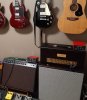
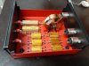
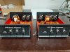
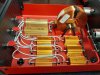
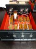
I'm impressed. Tube amps definitely sound better when they are turned up above 1 on the MV... Anyway, here are some pics. My enclosures are steel, hence the vertical mounting of the inductors.
 

Attachments

  • At home-774x883.jpg
    At home-774x883.jpg
    190.6 KB · Views: 161
  • Component placement-1209x907.jpg
    Component placement-1209x907.jpg
    380.9 KB · Views: 167
  • The pair half way done-1209x907.jpg
    The pair half way done-1209x907.jpg
    331.9 KB · Views: 165
  • Wired 1-1209x907.jpg
    Wired 1-1209x907.jpg
    432.3 KB · Views: 175
  • Wired 2-907x1209.jpg
    Wired 2-907x1209.jpg
    357.2 KB · Views: 165

JohnH

Well-Known Member
Joined
May 31, 2008
Messages
6,157
Reaction score
5,062
Location
Wilton NSW
Hi @LordoftheLivingRoom those look awesome!
What is your technique with the faceplate writing? (and I appreciate the name check)
Also, do you find any difference in how they are working on your amps? Two classic amp circuits there!

I'm nearly there with new cleaned-up diagram. No changes though, its basically what you built.
 
Last edited:

JohnH

Well-Known Member
Joined
May 31, 2008
Messages
6,157
Reaction score
5,062
Location
Wilton NSW
Here's a new drawing of Attenuator M2, stripped back to the basics, in 8 and 16 Ohm versions.


I think it is basically what @LordoftheLivingRoom has just built at 16 Ohm. There's no changes really to previous.

Ive not put in the full bypass, nor -3.5db-only resistive settings. These could be added (see M diagram on post 1), but after about 18 months, I don't think they are needed for most cases and leaving them off simplifies both for construction and use , reduces parts and electrical contacts, makes it much less likely to hook something up wrongly and takes the pressure off switching current for more reliability.

(work arounds if needed: To get a small -3db reduction, use the attenuator as a load box set to max attenuation, in parallel with the speaker, using 1/2 the amp tap ohms. And if you want full bypass, just unplug it and don't use it at all!)

I kept the 3rd output for using a 16 ohm cab with an 8 ohm attenuator. This is a useful tonal correction, but its quite safe to use the other outputs instead with a 16 ohm cab, you get a bit less treble, more mids. If you don't need this, or are building a 16 Ohm version, ignore everything in Red. And an 8 Ohm cab into a 16 attenuator should work fine as it is.

As before, power ratings for resistors allow for a cranked 50W amp, assuming case mounted resistors with thermal grease. For a 100W amp, values are the same, power ratings to be x2 and it might warrant a fan TBC.

The inductor is air cored, 18awg or thicker, and don't mount it with a steel bolt

I think I'm going to build another one like this!
 
Last edited:

Gene Ballzz

Well-Known Member
Joined
Feb 19, 2013
Messages
4,697
Reaction score
6,521
Location
Las Vegas, NV
@JohnH
Did we determine that the 19awg units that are easily and cheaply available from MADISOUND https://www.madisoundspeakerstore.c...wg/madisound-1.8-mh-19-awg-air-core-inductor/ would be robust enough in 16Ω unit for up to 50 watt amps? I thought we decided it was not completely necessary to double the price by bumping to 16awg, as well as the 16awg is a bit harder to mount through the switch and resistor lugs?

Just Re-Confirming?
Gene
 

JohnH

Well-Known Member
Joined
May 31, 2008
Messages
6,157
Reaction score
5,062
Location
Wilton NSW
@JohnH
Did we determine that the 19awg units that are easily and cheaply available from MADISOUND https://www.madisoundspeakerstore.c...wg/madisound-1.8-mh-19-awg-air-core-inductor/ would be robust enough in 16Ω unit for up to 50 watt amps? I thought we decided it was not completely necessary to double the price by bumping to 16awg, as well as the 16awg is a bit harder to mount through the switch and resistor lugs?

Just Re-Confirming?
Gene

Sure I think those ones are fine, and anyway they have worked well for you so far. Looking at different ranges from suppliers, 19awg seems quite rare, and 18 is more common. But a 1.8mH 18 gage that I can order has a resistance of 0.8Ohms, and the Maddisound at 19 gage is 0.85 Ohm, ie virtually the same. Also, with the M2 design, there is less total wire in it than the two coils in M and I think there is less current flowing through the coil.
 

Latest posts


Top