Esa Martikainen
Member
- Joined
- Jan 1, 2020
- Messages
- 40
- Reaction score
- 16
When here in Europe I have searched audio components often I have found them from from Holland and for my attenuator 15mH coil came from "audio.nl" and its link is here. Nowadays shipping is fast but quite costly as well.
https://audio.nl/Aprodview.asp?type=product&Product=1342
Esa
https://audio.nl/Aprodview.asp?type=product&Product=1342
Esa
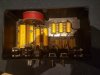
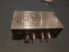

") I apologize if these images don't come thru ... I'm unfamiliar with how this interface (image/attachments) really works.
I apologize if these images don't come thru ... I'm unfamiliar with how this interface (image/attachments) really works.


