• We are looking to make improvements to the Classifieds! Help us determine what improvements we can make by filling out this classifieds survey. Your feedback is very appreciated and helpful!

    Take survey

Simple Attenuators - Design And Testing

  • Thread starter JohnH
  • Start date
  • This site may earn a commission from merchant affiliate links like Ebay, Amazon, and others.

JohnH

Well-Known Member
Joined
May 31, 2008
Messages
6,157
Reaction score
5,062
Location
Wilton NSW
hi @aceofbones and thanks for your interest.

Attenuators that have fx loops are generally the ones that work by reamping the signal, so that there can be a nice controlled line-level, low power signal to send out and receive back, before the amp stage. The signals in a passive attenuator like ours are not good for that, too much power flowing for units in such a loop. But as noted, you can have a line out and then feed that into an external amp system.
 

aceofbones

New Member
Joined
Sep 10, 2020
Messages
14
Reaction score
17
Ah, ok. Thanks for the clarification. It’s much appreciated.
I’ll find the last schematic with the line out on it and make sure I get the needed parts when I order everything else. Thanks again!
 

Oliver Gardiner

New Member
Gold Supporting Member
Joined
Nov 11, 2016
Messages
27
Reaction score
9
Hi John,

Thanks again for all your work here. While I was waiting for the power resistors to come from China, I knocked up an L-Pad using the Monacor AT-62H part - the design I followed included a switchable treble bleed cap, presumably as an attempt to compensate for lack of tone at high attenuation. It certainly does a job but I also discovered (which should have been obvious given the necessarily wire-wound elements) that its linear tapers give you no more than a quarter-turn of usable control. I eventually got all the bits for the M2 the other day and so have now given it a try. I've never had a particularly golden ear but I was genuinely surprised at how much difference there was between the two. Definitely worth the effort!

2020-09-10 08.10.04-1.jpg 2020-09-11 13.20.24.jpg 2020-09-12 08.59.24.jpg 2020-09-12 09.00.02.jpg
 

Oliver Gardiner

New Member
Gold Supporting Member
Joined
Nov 11, 2016
Messages
27
Reaction score
9
Not sure what variants there are - it's currently just a 10k pot across the speaker. I've always used a mic before and will probably be a while before I could try it with a PA. It's probably there for completeness and there was plenty of space no the front panel... What are the recommended options?

Thanks,

Oliver
 

JohnH

Well-Known Member
Joined
May 31, 2008
Messages
6,157
Reaction score
5,062
Location
Wilton NSW
A 10k pot is a good starting point. usually there will be a resistor in series with it on the hot side (ie from the speaker to the hot outer lug of the pot), maybe 2.2k (not critical). its job is mainly to be sure that nothing plugged into the line-out can short out the full signal.

If its at the end of the attenuator, at the speaker, it will pick up some speaker characteristics which is good, but its level will depend on how you set the attenuator. Some guys are putting them at the attenuator input = amp output instead. I think both are worth trying and you should experiment. But in any case, the line out wont be a good signal to go direct to a PA since it will have far to much treble because it doesn't have the acoustic roll off of a speaker. You'll need some form or cab-sim device, or better, an IR box.

One project I have is a passive cab-sim but I haven't tested it yet.
 

Filipe Soares

Well-Known Member
Joined
Mar 8, 2019
Messages
2,762
Reaction score
5,964
Location
RIO!
@JohnH what do you think about this build:

200 to 400w (to be decided) 16ohm reactive load to mute the amp, line leve transformer, class D ebay board to the speaker. making it 16ohms it would make it usable with 4 and 8 without harming too much the amp and the volume control would be totally seamless through the class d amp. no new idea here, that's what the waza amp do, but it's possible to make it super cheap and even with an added fx loop between the line level transformer and the class D amp board.
 

JohnH

Well-Known Member
Joined
May 31, 2008
Messages
6,157
Reaction score
5,062
Location
Wilton NSW
hi @Filipe Soares
The idea seems fine. I don't think you'd need a transformer, just a pot would do to set the input level to the Class D to match your amp output after the load. That would allow it to be set for different power tube amps. Then you'd have your main pot for setting the reduced output level.

I think the Class D amp has to be designed for the lowest speaker ohms you want to use.

The real design questions are around how much effort you put into the reactive load. It does two things, being a general rise in impedance with frequency to match coil inductance, and also the bass resonant peak. For the first, you need a $10 air-cored inductor - cheap and its the most important part. If you want to capture that bass peak too though, you also need a much bigger iron-core coil and a big-a$$ capacitor, and those alone can double the build cost. Google 'Aikens reactive load':

https://www.aikenamps.com/index.php/designing-a-reactive-speaker-load-emulator

https://www.thegearpage.net/board/index.php?threads/aikens-reactive-dummy-load.1072793/

The bass peak is around 100 hz, so it only comes into play if you are down on the low strings and low frets. If its not built in, you can always compensate a bit with a some more bass or resonance on the amp.

On this thread here, the designs that guys have built (M an M2) have just the treble inductor, the bass peak is generated by the real speaker interacting with the attenuator, but with an SS amp for the output, this would not occur. We also have design M3 with the bass circuit. Your reactive load could be a lot like Stage 1 of any of the designs on this thread. Happy to keep talking.
 

Oliver Gardiner

New Member
Gold Supporting Member
Joined
Nov 11, 2016
Messages
27
Reaction score
9
A 10k pot is a good starting point. usually there will be a resistor in series with it on the hot side (ie from the speaker to the hot outer lug of the pot), maybe 2.2k (not critical). its job is mainly to be sure that nothing plugged into the line-out can short out the full signal.

If its at the end of the attenuator, at the speaker, it will pick up some speaker characteristics which is good, but its level will depend on how you set the attenuator. Some guys are putting them at the attenuator input = amp output instead. I think both are worth trying and you should experiment. But in any case, the line out wont be a good signal to go direct to a PA since it will have far to much treble because it doesn't have the acoustic roll off of a speaker. You'll need some form or cab-sim device, or better, an IR box.

One project I have is a passive cab-sim but I haven't tested it yet.

Thanks again for the advice and good shout on the safety resistor on the pot. I may use the line out in the unlikely event that I wanted to record my dodgy playing but I'll keep an eye out for the passive cab sim and perhaps build that in at some point.
 

aceofbones

New Member
Joined
Sep 10, 2020
Messages
14
Reaction score
17
I’m very interested in @Filipe Soares‘s idea. That’s basically what I’m looking to do. After your(JohnH) answer to my question about an fx loop, I decided to just build the M2 with a line out and make a small power amp to feed a second cabinet. However, if there’s a feasible way to do it in one box that would be fantastic. I have already ordered all the parts for the M2.
Do you see this as a possible other direction someone could take your work or would it end up compromising the functionality of an already proven design?
 

JohnH

Well-Known Member
Joined
May 31, 2008
Messages
6,157
Reaction score
5,062
Location
Wilton NSW
hi @aceofbones
There's definitely a possible design in what you say. My view is that to get it from idea to finished design is probably not a one-step process, but rather one that needs some testing,/prototyping to get it right and find and iron out any bugs.

Id suggest to get the M2 working with a line-out, and make a test-bench build of the amp section separately, so you can check for levels at different stages, power supply, tone and what values of pots or any trimmers needed and how the fx loop will work. Then if it seems like its worth pursuing you can chose whether to build it into the M2 or to build it as a separate unit.

For this arrangement you need line-out via a pot from the attenuator input ie the real amps output

My question about it is, as for Filipe, how it will sound in the low bass without the bass resonance circuit since the speaker won't be interacting with the attenuator to create the bass peak, as it does in the M and M2 passive designs.

It might be handy to have both passive and active options, but if you end up just using the active amp output, then you might not need all the switched passive stages.

If I ever get any time, I can test some of this using my M build as a load box, and getting a line-out signal to feed into the poweramp section of my old PowerBlock amp, which when you plug in after its preamp is just a linear clean Class D.
 

Oliver Gardiner

New Member
Gold Supporting Member
Joined
Nov 11, 2016
Messages
27
Reaction score
9
A 10k pot is a good starting point. usually there will be a resistor in series with it on the hot side (ie from the speaker to the hot outer lug of the pot), maybe 2.2k (not critical). its job is mainly to be sure that nothing plugged into the line-out can short out the full signal.

If its at the end of the attenuator, at the speaker, it will pick up some speaker characteristics which is good, but its level will depend on how you set the attenuator. Some guys are putting them at the attenuator input = amp output instead. I think both are worth trying and you should experiment. But in any case, the line out wont be a good signal to go direct to a PA since it will have far to much treble because it doesn't have the acoustic roll off of a speaker. You'll need some form or cab-sim device, or better, an IR box.

One project I have is a passive cab-sim but I haven't tested it yet.

Presumably, the output of the first 7dB stage would also be an option in terms of the level being stable - will have a play. Having done a bit of poking around, I think I'll start with the Simple Cab Sim R2 by Lart but I'll keep it external to the attenuator
 

JohnH

Well-Known Member
Joined
May 31, 2008
Messages
6,157
Reaction score
5,062
Location
Wilton NSW
Presumably, the output of the first 7dB stage would also be an option in terms of the level being stable - will have a play. Having done a bit of poking around, I think I'll start with the Simple Cab Sim R2 by Lart but I'll keep it external to the attenuator

Can try it, but it may not be best and may sound a bit dull.

One of the tricks of the M and M2 designs is that the tone that travels through the attenuation stages after Stage 1 is mostly neutral, without the reactive phase effects which are balanced out by the part series part parallel arrangement of the coil or coils.. This enables it to step down using resistors without changing. Then when it reaches the speaker, the speaker recreates the correct tone by its own reactance, as it would if fed directly from an amp.

So the best tonal balance for taking a line out is at the speaker, or at the input where it is affected by the coil.
 

aceofbones

New Member
Joined
Sep 10, 2020
Messages
14
Reaction score
17
Thanks very much. I will complete the M2 then play around with some ideas.
Cheers!
 

Mcentee2

Active Member
Joined
Jan 17, 2020
Messages
312
Reaction score
162
Location
York,UK
Hi all, back with a question I should already know.

I have been thoroughly enjoying my M2 build for a few months now, but have recently got an extra 8r cabinet that plugs into my SV20 head along with its current 8r cab.

I can plug them both directly I to the sv20 in the "2x8r" sockets, ....hmmmm I would need two attenuators here!

or I can plug one into the extension jack of the other and take that back to the "1x4r" on the sv20.

Hurrah!

..but, I built an 8r M2.

With the 4r parallel speaker cabs plugged into the back of the M2 I am reading this on the amp input jack:

-7db 7.6r
-14db 8.6r

So, is this ok to plug into a 1x8r output on the SV20 for both?

With a 4r actual speaker load, are the M2 stages still -7db and -14db, or has this changed ?

IIRC from previous posts, quite a few pages now, from the speakers' point of view, now a total 4r, they are happy with the input impedance of the amp/attenuator anyway.

I know if I use the M2 bypassed I will need to repatch it to the 8r output until I can build a 4r version.

Which brings me to :

is there a quick and easy way to get my M2 to a 4r version ?

I'm thinking it isn't as simple as toggling a high power 8r in parallel with the whole thing?
 
Last edited:

JohnH

Well-Known Member
Joined
May 31, 2008
Messages
6,157
Reaction score
5,062
Location
Wilton NSW
Hi @Mcentee2

Good questions, and there's good news:

Provided that at least the first -7db stage is on, it should work fine with a four ohm load on the attenuator, and using the 8 Ohm amp tap. You checked the resistance seen by the amp and it still stays close to the 8 ohms that the amp expects. The attenuation levels stay close to the same but with about another -1to -2 db attenuation through the mids compared to bass and high treble. You may not be able to hear this difference, but if you wanted to compensate, a small reduction in amp resonance and presence should fix it.

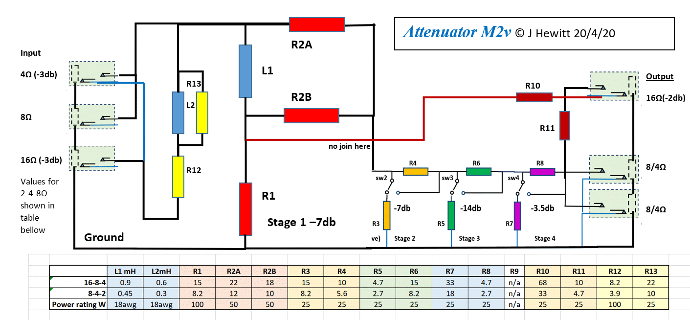
For using different amp taps, weber uses just a parallel resistor, but if you do that you partly loose the benefits of the reactive input. I worked out an add-on comprising another coil and two resistors which you can put in series with the input to convert to 16 ohms or in parallel to convert to 4 ohms. But in either of these cases, all attenuations drop another -3 db.

The diagram below has values to take a base 8 Ohm M2 and use it with 16, 8 or 4 ohm taps, or to start with a 4 Ohm M2 and use 8, 4 or 2 ohm amp taps (useful for certain old Fenders)


Gene Ballzz

Well-Known Member
Joined
Feb 19, 2013
Messages
4,697
Reaction score
6,521
Location
Las Vegas, NV
WOW @JohnH !
That is a really great revision! With a "post attenuation" line out, that would be a pretty much one size fits all (well two really, 16-8-4 and 8-4-2) with all of the bells, whistles and options!
Great Job!
Gene
 

JohnH

Well-Known Member
Joined
May 31, 2008
Messages
6,157
Reaction score
5,062
Location
Wilton NSW
Hopefully it's a useful idea for those with multiple different amps. I dont think it should affect the tone significantly. Just have to take account that the added front end parts take half the power when they are running so hence the added -3db drop.
 

Mcentee2

Active Member
Joined
Jan 17, 2020
Messages
312
Reaction score
162
Location
York,UK
Hi @Mcentee2

Good questions, and there's good news:

Provided that at least the first -7db stage is on, it should work fine with a four ohm load on the attenuator, and using the 8 Ohm amp tap. You checked the resistance seen by the amp and it still stays close to the 8 ohms that the amp expects. The attenuation levels stay close to the same but with about another -1to -2 db attenuation through the mids compared to bass and high treble. You may not be able to hear this difference, but if you wanted to compensate, a small reduction in amp resonance and presence should fix it.

For using different amp taps, weber uses just a parallel resistor, but if you do that you partly loose the benefits of the reactive input. I worked out an add-on comprising another coil and two resistors which you can put in series with the input to convert to 16 ohms or in parallel to convert to 4 ohms. But in either of these cases, all attenuations drop another -3 db.

The diagram below has values to take a base 8 Ohm M2 and use it with 16, 8 or 4 ohm taps, or to start with a 4 Ohm M2 and use 8, 4 or 2 ohm amp taps (useful for certain old Fenders)


Many thanks!

Glad I planned ahead, as I have a spare 0.6mH inductor left from my M2 build and maybe space on the enclosure :)

I also have 2x16r, 1x12r and 1x8r all 25w, which I put together to make:

2x16r in parallel = 8r 50w for R12
1x8r and 1x12r series = 20r 50w for R13

These aren't exact but are probably close enough.

The extra -3db isn't something I was looking for, but might be liveable with.
 

crashcarlson

New Member
Joined
Sep 23, 2020
Messages
11
Reaction score
3
@JohnH

All the work you've done here is just awesome! I did have one question on your schematics - I'm familiar with soldering, but I had a question on your symbols you're using. Specifically, I want to make "Design C" on post #68 way back on page 4 (for a 16 ohm amp output and a 16 ohm cab). I'm just not sure which is tip (signal) and sleeve (ground) for the jacks. Would I be right in assuming that the "top left" side (input from amp) has the tip (signal) of the jack connecting to R2, and the sleeve (ground) connects to R1? And then the bottom part of the circuit (R1 to R3 to R5) ends up terminating at the sleeve on the output jack? Is there any other grounding (like to the enclosure itself), or is that it?

Thanks!
 

Latest posts


Top