• We are looking to make improvements to the Classifieds! Help us determine what improvements we can make by filling out this classifieds survey. Your feedback is very appreciated and helpful!

    Take survey

Simple Attenuators - Design And Testing

  • Thread starter JohnH
  • Start date
  • This site may earn a commission from merchant affiliate links like Ebay, Amazon, and others.

JohnH

Well-Known Member
Joined
May 31, 2008
Messages
6,157
Reaction score
5,062
Location
Wilton NSW
I'll delete or modify this post, but is there a recommended source / part # for the inductors ?
Bypass switch if used should be a " shorting [ MBB ] " to not leave the amp with no load when switching? If someone points me to the correct page with inductor info I'll change this post thanks.

Hi @okgb - good questions (worth asking!) The inductors tend to come from places that sell cross-over components for speakers. In the US, Madisound has the goods. They do a range in 19 ga which is fine for the 50W versions. They do 16 ga too, which would be good for 100W builds. Where are you? Happy to dig deeper and pot a product.

For a bypass switch, yes I guess mbb is best, but its moot because I would never recommend switching a full bypass switch on the fly. Always put the amp into standby while you do it. That would apply to any attenuator.


hi @_Steve , actually nobody has asked about doing a 300W version before! What would you be using it with? The power doesn't change the values but all power and current ratings and gages would go up for wire, coil, resistors and switches. And also jacks. It would depend if you really intendrd to push such an amp, and also what ohms its for. Also, it would need powered fan cooling and be built big and open to spread heat.

The power ratings per the diagrams are based on the nominal amp power, allowing that they may get pushed. On that basis, 50W ones seem to stay reasonably cool/not too hot, if built with good venting and heavy chassis, and by 100W, if cranked, more serious heat is created needing better active cooling.
 

_Steve

Well-Known Member
Joined
Apr 29, 2020
Messages
669
Reaction score
653
Location
Los Angeles
Hi @okgb
hi @_Steve , actually nobody has asked about doing a 300W version before! What would you be using it with? The power doesn't change the values but all power and current ratings and gages would go up for wire, coil, resistors and switches. And also jacks. It would depend if you really intendrd to push such an amp, and also what ohms its for. Also, it would need powered fan cooling and be built big and open to spread heat.

The power ratings per the diagrams are based on the nominal amp power, allowing that they may get pushed. On that basis, 50W ones seem to stay reasonably cool/not too hot, if built with good venting and heavy chassis, and by 100W, if cranked, more serious heat is created needing better active cooling.

OK got it thanks, so same Henries, heavier guage.

I should have said 150W sorry. 300W was in my head as the rating of R1 needed to handle a 150W amp. Im currently building a 120W Hiwatt with 6xEL34, and in the future I want to play with KT88s in various Marshall builds. So having a decent rated attenuator will be needed even just for testing on the bench.

Do you think 14, or even 16AWG will be OK for (max) 150W?
 

JohnH

Well-Known Member
Joined
May 31, 2008
Messages
6,157
Reaction score
5,062
Location
Wilton NSW
ok, that sounds more feasible! But what amp ohms will you build it for? if you can use a 16 Ohm tap, then there's less current than for 8 Ohms at the same power.
 

_Steve

Well-Known Member
Joined
Apr 29, 2020
Messages
669
Reaction score
653
Location
Los Angeles
ok, that sounds more feasible! But what amp ohms will you build it for? if you can use a 16 Ohm tap, then there's less current than for 8 Ohms at the same power.

Good point, however I think I need to at least accommodate 8ohms. Maybe I can do without 4ohms.

Can I use the standard EE guidelines for AWG vs current? Or is it different in inductors?
 

JohnH

Well-Known Member
Joined
May 31, 2008
Messages
6,157
Reaction score
5,062
Location
Wilton NSW
ok the basic M2 can be built to any one given amp tap, then you can use it with speakers of that or x2 or x1/2. So an 8ohm build?

In that case you'll have about 4.5 Amps at 150W. So really good jacks needed. If you can live without full byoass switch I'd recommend it. on the inductor wire, id go bigger than EE ratings just so it doesn't heat up too much. id expect 16ga would be ok but 14 would be better. Id use 16 for hook up.
 

_Steve

Well-Known Member
Joined
Apr 29, 2020
Messages
669
Reaction score
653
Location
Los Angeles
ok the basic M2 can be built to any one given amp tap, then you can use it with speakers of that or x2 or x1/2. So an 8ohm build?

In that case you'll have about 4.5 Amps at 150W. So really good jacks needed. If you can live without full byoass switch I'd recommend it. on the inductor wire, id go bigger than EE ratings just so it doesn't heat up too much. id expect 16ga would be ok but 14 would be better. Id use 16 for hook up.

Perfect. Great info as always thanks!
 

stareIO

New Member
Joined
Sep 18, 2020
Messages
2
Reaction score
0
@JohnH thank you for this generous gift to the community, especially during these trying times! Will make using my old 50W Jubilee combo while housebound a lot more fun.

I'm putting a parts list together for a simple 1-in/1-out 8 ohm M2 and have sourced all of the 'important' bits (the aluminum-housed resistors and inductor) -- I'm having trouble finding recommendations for the 'basics' (jacks and switches).

For the jacks, I'm curious if I need, or if there's an advantage to, TRS versions vs. TS? Should they be switched or non-switched? I assume all plastic or nylon housings, threads, nuts, etc. (I'd seen this mentioned earlier in the thread)? I see several Neutrik, or Neutrik-Rean, parts that look like they would work but wanted to be sure (I'm in the US).

And for the toggle switches, should they be SPST or SPDT (was planning to go with 5A or greater current capacity as mentioned earlier in the thread)? How many lugs should be on the back of each?

Thanks for any help you (or others) could provide, and thanks again for a design blueprint with a lot of thought and care behind it. I've build a very simple (L pad-based) attenuator a few years ago but wasn't happy with the results (seemed to 'deaden' the sound), looking forward to something with more design/intelligence behind it (as well as a nice little winter project).

Cheers!
 

JohnH

Well-Known Member
Joined
May 31, 2008
Messages
6,157
Reaction score
5,062
Location
Wilton NSW
hi @stareIO and thanks for posting

On the switches you need single-pole, double throw SPDT as a minimum, which means one central lug can connect to either of two outer lugs, so three lugs in a line. SPST would just have two lugs. But you can also get double pole double throw, DPDT which is two separate SPDT's next to each other , with 6 lugs. These are very common and not much more. They can have a small advantage if you link across horizontally each of the three pairs of lugs so the two sides work in parallel. This doubles the current capacity and adds reliability. Not essential though.

For jacks, they should be fully insulated from the chassis, so likely to be plastic bodied. For what you are building, just simple mono jacks are OK. I like the TRS ones though because the extra ring connection adds grip to the plug - but im only buying generic cheap sockets. I use the ring terminal electrically for the extra 16 ohm output in an 8 ohm M2 and to control variable inputs on M2V, but with 8 ohms and one in one out, you don't need it. Neutric is a good brand. Actually, none of the designs need a switched jack but you can use one if that's what you have.

Good luck with the build! Lets us know how it goes.
 

stareIO

New Member
Joined
Sep 18, 2020
Messages
2
Reaction score
0
Copy all of the above -- thanks for the much needed help! Will post back when I get everything further along. All the best to you! Essential thread!
 

Baby Thomas

New Member
Joined
Jul 15, 2019
Messages
11
Reaction score
2
Great point about using both sides of a DPDT switch for double the current, I did mine the same way. Also you have something like a fail-safe protection (if one of the contacts "dies").
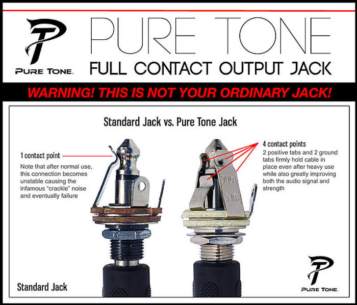
For the jacks - Neutik all the way! But another good option is Pure Tone, the image explains it all:
puretonejacksheet.jpg
 

TheOtherEric

Active Member
Joined
Oct 25, 2020
Messages
155
Reaction score
166
Thanks @JohnH for all your hard work on this amazing project! Have you (or anyone) found any real benefits to using Mouser (1% tol) resistors over ebay/chinese (5% tol)? The Mouser (Ohmite/Vishay) total approx $50 for a basic 9-resistor M2 build, whereas the ebay parts run $20. (Adding $30 cost to a $75 build is a lot!) I know there's the lead time issue (3-5 days vs 3-5 weeks) and potential quality/reliability, but I'm wondering what impact 5% tolerances may have on sound quality. I don't know enough about the model's sensitivity to know how the tolerances might shift the performance curves nor about how a shifted curve might affect sound quality.

I guess half the answer would be found in Monte Carlo simulations, ha ha, but let's not go down that road!
 

JohnH

Well-Known Member
Joined
May 31, 2008
Messages
6,157
Reaction score
5,062
Location
Wilton NSW
Hi @Baby Thomas - I like the idea of those Puretone jacks with the doubled contacts, id definitely use them in guitars. But as shown, the jack barrel is connected to the body, which means for the attenuator, one of the OT taps will be live to the case - not good.

Hi @TheOtherEric - Ive just used the chinese ones, I think they are fine. The design is not critical for precise tolerances and 5% is perfectly OK. Actually, I have had to adapt the values used to work with available standard ranges anyway, which tend to be in about 20% increments.

Within these kind of variations, you wont hear a difference in tone, and the amp doesn't care either. The ranges available from China are often not the same series of steps as in a standard resistor range, and may have gaps. This is the link Ive used:

https://www.ebay.com.au/itm/25-50-1...af460118a:g:EqkAAOSwzoJfh5k3&var=692191819131

Its from ebay.au, but Im sure you can find it. I haven't bought any more since covid, but I had several packages last year. He shipped within a day, and then you wait......
……….but they do arrive. That's the best ebay range Ive seen and gets most of the key ones, but the values aren't all as standard. eg You have to use 5 and 6 instead of 4.7 and 5.6. Also, there's a big gap around 33, 50, 75.

If you sub different values within say 10% of the design, the only implication is slight unevenness in the available steps of attenuation - it still works and sounds fine. The key thing is the ratio between the resistors within each stage. I had some 5W and 10W ceramic resistors around and in one case I put a high value one in parallel with a power resistor to bring it down slightly - just because I could.
 

TheOtherEric

Active Member
Joined
Oct 25, 2020
Messages
155
Reaction score
166
... That's the best ebay range Ive seen and gets most of the key ones, but the values aren't all as standard. eg You have to use 5 and 6 instead of 4.7 and 5.6. Also, there's a big gap around 33, 50, 75.

If you sub different values within say 10% of the design, the only implication is slight unevenness in the available steps of attenuation - it still works and sounds fine. The key thing is the ratio between the resistors within each stage. I had some 5W and 10W ceramic resistors around and in one case I put a high value one in parallel with a power resistor to bring it down slightly - just because I could.
Thanks for the help, and for the points about R selection, which I was puzzling over since the ebay seller I found had no 75R or 12R for the -3.5dB stage, just 68 or 80R and 10 or 13R. Closest I can get to preserving the ratio is 80R and 13R I guess.
 
Last edited:

Gene Ballzz

Well-Known Member
Joined
Feb 19, 2013
Messages
4,697
Reaction score
6,521
Location
Las Vegas, NV

TheOtherEric

Active Member
Joined
Oct 25, 2020
Messages
155
Reaction score
166
Here's a little help for anyone contemplating the project, which I'm posting since I haven't come across detailed parts lists. Just got everything ordered for a basic M2, and the costs are quite a bit lower than expected! (Note I'm actually building two, 8R and a 16R, but I'm showing avg costs for one assembly to avoid confusion).

A. Parts Express
1. Inductors. Jantzen 18g $11.
2. Feet. 4-pack .69"D x .39"H, #260-7514. $1.25
3. Thermal paste, #NTE303 $3
4. 1/4” jacks. Neutrik #090-972 $1.12x3
5. Switches. SPDT $1.69x3=$5
6. Hookup Wire, 18g #101-729, $5.
Subtotal, Parts Express incl tax, shipping = $37

B. Other
7. Resistors. From eBay (socoolmart) incl ship, tax = $19. From Mouser = $53 (hint- select Mouser's category Wirewound Resistors - Chassis Mount).
8. Project box. From eBay 200x106x55mm incl ship,tax = $18 (link)
9. Screws and nuts (size M3) = $5

TOTAL incl. tax, shipping = $79 if eBay resistors. $113 if Mouser resistors.
 
Last edited:
As an eBay Associate we earn from qualifying purchases.

foil1260

New Member
Joined
Sep 27, 2020
Messages
4
Reaction score
0
I've collected all the parts I think I need for the M2 design, but I'm a relative beginner in terms of wiring and I was hoping someone here might be gracious enough to have a look at this layout I had planned. Apologies that it's kind of a mess, I tried to make all the wires contrasting colors so they would be easier to track.

When I first started on this project, I figured it would be easy enough with the diagram, but I soon realized I had questions about the order that things are wired in, or whether that actually matters. As an example, should lug 3 of the switch for stage 2 go to the lug on R4 first, then to the lug on R6, and then to lug 2 on the stage 2 switch? Or should they all meet together at lug 2 on the stage 2 switch?

In any case, my attempt at laying everything out is in the diagram, and I appreciate any help.
 

Attachments

  • Untitled.jpg
    Untitled.jpg
    148.2 KB · Views: 58

JohnH

Well-Known Member
Joined
May 31, 2008
Messages
6,157
Reaction score
5,062
Location
Wilton NSW
hi @foil1260
I can't see any errors in the wiring.

In these devices, it doesn't matter how you run the wires, so long as what needs to be connected is so. So a run of wire A to B to C is the same as B to A to C, or A, B and C all to one point. So you can pick wire runs for the shortest or neatest results.

When you have all the parts, you might lay them out and decide to amend the wiring due to the relative sizes and locations.

You can also consider whether wiring with no more that a couple of wires per lug is easier than with more and move a connection to the other end of a wire if that's easier. None of these changes would affect the schematic diagram. Note, while the above is a typical principle for many circuits, some need careful attention to where wires actually go physically, eg where there is mains involved or high-gain stages and also sensitive input stages. That applies in an amp but not in a separate attenuator.

Note that I laid out the three switched stages as I did, for some smallish electrical reasons so the stages go -7(reactive), -7, -14 then -3.5. But you may prefer to physically place the switches for the three switched stages in an order like -14, -7, -3.5. Then its like binary numbers, each one is twice the one to the right
 

JohnH

Well-Known Member
Joined
May 31, 2008
Messages
6,157
Reaction score
5,062
Location
Wilton NSW
Here's a little help for anyone contemplating the project, which I'm posting since I haven't come across detailed parts lists. Just got everything ordered for a basic M2, and the costs are quite a bit lower than expected! (Note I'm actually building two, 8R and a 16R, but I'm showing avg costs for one assembly to avoid confusion).

A. Parts Express
1. Inductors. Jantzen 18g $11.
2. Feet. 4-pack .69"D x .39"H, #260-7514. $1.25
3. Thermal paste, #NTE303 $3
4. 1/4” jacks. Neutrik #090-972 $1.12x3
5. Switches. DPDT 10A #299-554 $1.69x3=$5
6. Hookup Wire, 18g #101-729, $5.
Subtotal, Parts Express incl tax, shipping = $37

B. Other
7. Resistors. From eBay (socoolmart) incl ship, tax = $19. From Mouser = $53 (hint- select Mouser's category Wirewound Resistors - Chassis Mount).
8. Project box. From eBay 200x106x55mm incl ship,tax = $18 (link)

TOTAL incl. tax, shipping = $74 if eBay resistors. $108 if Mouser resistors.

Thanks for this list.

Particularly, that socoolmart eBay link for the chinese resistors looks very useful. They appear to be the same as I was getting but, they have a better standard range of values across 100W, 50W and 25W ratings that hit all the values that we need.
 
As an eBay Associate we earn from qualifying purchases.

steka

New Member
Joined
Dec 15, 2020
Messages
5
Reaction score
6
Ok, John you got me on the hook. Joined this board just to participate in this discussion - and i don‘t even own a Marshall amp (anymore or... yet?).
Interested in the M2 wiring, but have a question or two.

  1. I can‘t seem to get an air core inductor at 0.9mH. I only have an option at 1 mH with a height of 18mm (this was referenced as the preferred size before). What would be the implication from that?
  2. How can i test the circuit without risking my amp? Any possibility with a standard circuit tester?
  3. Wire diameter - what is recommended?
 

JohnH

Well-Known Member
Joined
May 31, 2008
Messages
6,157
Reaction score
5,062
Location
Wilton NSW
Hi @steka, thanks for joining!

im assuming you are in the US? and interested in an 8 ohm version?

1mH is fine

Once its built, you can test it with a multimeter set to Ohms. Even a cheap one is fine for this. With a speaker plugged in, the resistance measured across the input jack, ie what the zmo sees, should measure between about 7 and 10 ohms in all settings

I use 18 gage for hookup wire.

good luck!
 
Top