musicheals
New Member
- Joined
- Jun 3, 2021
- Messages
- 11
- Reaction score
- 7
@JohnH
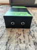
Is there a way, to use your M2 also as a dummy for recording?
If yes, where is the best place, to put in a line out?
Thanks a lot
musicheals

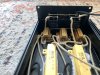
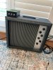


That certainly looks hefty! I thought about doing something similar. I bet the aluminum cost as much as all the other parts.This took a little longer than I thought, due to the amateur metal fabrication. I wanted something a little heftier than the project boxes most people use.
But whether or not S5 is engaged, it's safe to put any 4, 8 or 16 cab into the output, using either 8 or 16 input.
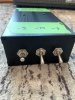
Here's a new variant based on M2. It's aimed at getting a more versatile option for a unit to work across different amp and cab impedances.
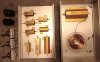
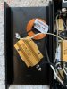
I got all the parts now. I didn't order in China. I bought at my long time supplier Reichelt in Germany. It was no big difference in price. Only the big guy was around 7€. I attach a picture...That's great! I thought I have to build me reactive load.
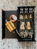
Today I will order all parts. When I finished your attenuator, I will review and send some photos...
Thanks a lot John
musicheals
I got all the parts now. I didn't order in China. I bought at my long time supplier Reichelt in Germany. It was no big difference in price. Only the big guy was around 7€. I attach a picture...
Thanks
musicheals