• We are looking to make improvements to the Classifieds! Help us determine what improvements we can make by filling out this classifieds survey. Your feedback is very appreciated and helpful!

    Take survey

Simple Attenuators - Design And Testing

  • Thread starter JohnH
  • Start date
  • This site may earn a commission from merchant affiliate links like Ebay, Amazon, and others.

Blaoskaak

Active Member
Joined
Jun 27, 2020
Messages
170
Reaction score
99
Just giving us a small bump back to our usual place near the front of the workbench! Also, congrats to @Blaoskaak who got his M2 running successfully.

Here's one thing I'm very happy about: 93 pages in and countless builds later, every single build based on this thread that has gone ahead and been reported here, has been a success.

Thanks! I'm very very happy with the attenuator! It really sounds amazing. In fact, it sounds so good that I took the pedals out in between too.

I can shoot some pics when i'm home for the one's who are interested.

Thank you @JohnH too! Without your help it would never worked. :applause:
 

Graham G

Well-Known Member
Joined
Feb 4, 2018
Messages
252
Reaction score
359
Hi guys,i'm UK based & i'm struggling to source the L1 inductor spec'd in the M2 attenuator, it's probably not helping that I don't really understand the spec ratings :confused:, CPC are showing Visaton (german) conductors but not the spec on Johns list, can anyone help ? Cheers.:)

Can I also ask if there's a preference or spec for the 3 switches.
 
Last edited:

JohnH

Well-Known Member
Joined
May 31, 2008
Messages
6,155
Reaction score
5,062
Location
Wilton NSW
Hi Graham

The inductor tends to come from places that sell crossover components for loudspeakers. There are two styles, either wound on a plastic bobbin, or wound just on itself and secured with zip ties and both are fine. The wire gage should be 18 awg, which is also 1mm diameter.

heres one in EU for the 0.9mH inductance:
Looking for a Dayton Audio LW18-90 crossover coil? - SoundImports

Some ranges don't have the 0.9mH, but in truth, the difference that you will hear is negligible between 0.82mH and 1mH, which opens up some more options, eg:

Visaton SP Air-Core Coils – Impact Audio
product 5013 or 5014 looks fine

there are heaps of hifi component places in the UK, so you may find other options.

In mounting, dont use a normal steel bolt, and best to add about a 5mm plastic or wood spacer against the metal case , to stop it affecting the value.

Switches will be two position, and may be called on-on. Definitely not on-off-on which is three position. Rating should be 5A amps at 125V or better.

Most use standard toggle switches which mount into a 10 or 12mm hole. there are also mini-toggles that go into a 6.5mm hole, which can still have that rating but they are more of a fiddle to wire up with the fairly thick wire we use.
 

Graham G

Well-Known Member
Joined
Feb 4, 2018
Messages
252
Reaction score
359
Thanks John, thanks for the link, I now realise that these are the type of coils/components used in passive x-overs in Hi Fi speakers :rolleyes:
really appreciate the info & help.
 
Last edited:

Graham G

Well-Known Member
Joined
Feb 4, 2018
Messages
252
Reaction score
359

donwagar

Well-Known Member
Joined
Nov 24, 2018
Messages
254
Reaction score
694
Location
Calgary, Alberta
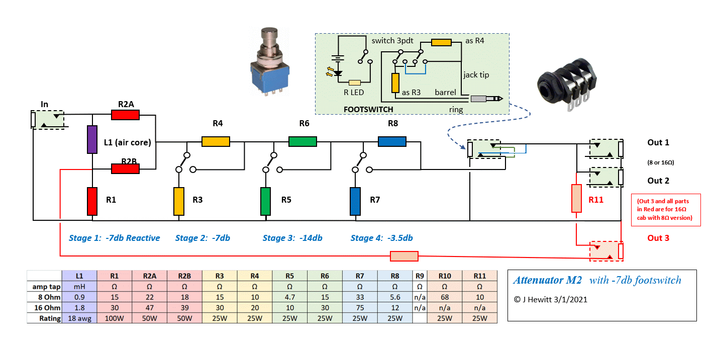
Footswitch -3.5dB Stage

full


Someone on one of the SV20 threads mentioned it might be good to have a footswitchable attenuator to cut just the volume (without losing tone). I thought that was a brilliant idea. An easy way to go from rhythm to solo volumes.

I was just starting to plan to build an M2, so I asked JohnH if it was possible. He already had a schematic for it.

I finally finished it, it works great. (I still have to collect the parts and add an LED to it).

Because the SV20 already has a 5W switch, and because I'm not planning on using it at home (I keep it in our practice space, only use it for practices and gigs), I left the -14dB Stage out of mine.

So it has -7 (reactive), -7 and -3.5 switchable, and -3.5 on the footswitch. My amp is the SV20C combo, so one speaker, so I only used one speaker jack.

I think this attenuator is fantastic, anyone that is reasonably handy really should build one.

[Gene noticed the original jacks I used weren't isolated, thanks for that, fixed now]
 
Last edited:

Rvenn

New Member
Joined
Sep 10, 2021
Messages
1
Reaction score
0
Hi Everyone, AWESOME thread thanks, extremely interesting & buckets of great info & build inspiration!

One question I don't think has been asked:
I've got a Dayton 0.9mH air core inductor kicking around that's 20awg and 0.71 Ohm, Would this be ok to use in L1 or should I really get a 18Awg inductor? (which are closer to 0.49ohm)

I only plan on running a 15W or 20W amp through the attenuator at most, but cant ascertain if the lower resistance value is important

Cheers
 

JohnH

Well-Known Member
Joined
May 31, 2008
Messages
6,155
Reaction score
5,062
Location
Wilton NSW
Hi @Rvenn , welcome to our thread and thanks for your interest in this design.

A 20awg coil will probably work fine, but it will get hotter and push the ohms seen by the amp slightly. Try it if you like, but I think 18awg is the best type.
 

zfrittz6

New Member
Joined
Sep 11, 2021
Messages
3
Reaction score
0
Hello, a crazy idea, if in the 8 Ohm output of the transformer of an amplifier we put an 8 ohm load, and then we make a third winding of, let's say 0.1 ohm, and we connect an 8 ohm speaker ...
What impedance would the outlet valves see?
Would the sound of the amp change?
If the impedance is not greatly affected, the transformer could be modified to have various powers, from 0w to 1 w to play at home, and since it does not have resistors or anything to attenuate the signal, the sound should be the same as the original.
Greetings
 

matttornado

Well-Known Member
Joined
Mar 14, 2012
Messages
1,900
Reaction score
1,510
Footswitch -3.5dB Stage

full


Someone on one of the SV20 threads mentioned it might be good to have a footswitchable attenuator to cut just the volume (without losing tone). I thought that was a brilliant idea. An easy way to go from rhythm to solo volumes.

I was just starting to plan to build an M2, so I asked JohnH if it was possible. He already had a schematic for it.

I finally finished it, it works great. (I still have to collect the parts and add an LED to it).

Because the SV20 already has a 5W switch, and because I'm not planning on using it at home (I keep it in our practice space, only use it for practices and gigs), I left the -14dB Stage out of mine.

So it has -7 (reactive), -7 and -3.5 switchable, and -3.5 on the footswitch. My amp is the SV20C combo, so one speaker, so I only used one speaker jack.

I think this attenuator is fantastic, anyone that is reasonably handy really should build one.

[Gene noticed the original jacks I used weren't isolated, thanks for that, fixed now]

That's awesome! I was just thinking of that the other day. I'm interested in doing that as well. Does the speaker signal run through the footswitch? That would be bad news for sure.

Can someone repost the schematic showing the footswitch idea?

thanks!!!
 

matttornado

Well-Known Member
Joined
Mar 14, 2012
Messages
1,900
Reaction score
1,510
For a -3.5db footswitch, do you just simply replace the -3.5 db toggle switch on the attenuator with a 1/4" female jack and run a cord to a typical footswitch?
 

JohnH

Well-Known Member
Joined
May 31, 2008
Messages
6,155
Reaction score
5,062
Location
Wilton NSW
That's awesome! I was just thinking of that the other day. I'm interested in doing that as well. Does the speaker signal run through the footswitch? That would be bad news for sure.

Can someone repost the schematic showing the footswitch idea?

thanks!!!

This was the diagram:


The signal does go out to the footswitch and back, via a special 3-core cable made using 5A mains flex and stereo jacks. But It's not the whole current, it's already attenuated. For a typical 50W 8ohm build, it's about 1.1A max. On the footswitch, two of the three poles are used in parallel to get plenty of current rating. And a typical 3pdt such as you build into a stomp box, has a rating of 4A at 125V per contact anyway.

If the footswitch is not plugged in, then the switched jacks sends the signal through to the speaker

I think this idea is ok provided the first reactive stage is always on, so not using it for a full bypass.
 
Last edited:

JohnH

Well-Known Member
Joined
May 31, 2008
Messages
6,155
Reaction score
5,062
Location
Wilton NSW
Hello, a crazy idea, if in the 8 Ohm output of the transformer of an amplifier we put an 8 ohm load, and then we make a third winding of, let's say 0.1 ohm, and we connect an 8 ohm speaker ...
What impedance would the outlet valves see?
Would the sound of the amp change?
If the impedance is not greatly affected, the transformer could be modified to have various powers, from 0w to 1 w to play at home, and since it does not have resistors or anything to attenuate the signal, the sound should be the same as the original.
Greetings

Not sure, but I think it might work. But to sound right, I'd say that the load would need to be a properly designed reactive load rather than just a resistor

The idea could maybe be adapted to work with amps as they are.

The following is pure speculation, don't try it unless you understand, accept and agree!

Studio amps, current DSLs and many classic amps have a full group of output taps, 4, 8 and 16. If you plug a 16 cab
into the 4 tap, it's giving 1/4 of the load the amp needs.

Then, use a reactive load worked out for 8 ohms x 4/3 and put it in the 8ohm tap, to give the other 3/4 of the load. The amp is now fully and properly loaded by reactive loads, and the actual speaker is drawing 1/4 the power, a -6db attenuation.

Maybe?
 

zfrittz6

New Member
Joined
Sep 11, 2021
Messages
3
Reaction score
0
Hello, I am sorry I do not know how to calculate a reactive load, if you have any scheme of some to use it, I could test my theory.
 

JohnH

Well-Known Member
Joined
May 31, 2008
Messages
6,155
Reaction score
5,062
Location
Wilton NSW
Hello, I am sorry I do not know how to calculate a reactive load, if you have any scheme of some to use it, I could test my theory.

This is the classic thread about reactive load boxes:
Aiken's Reactive Dummy Load. | The Gear Page

You can also use our attenuator on this thread as a reactive load (switch to full attenuation and no speaker in it).

For your idea, adding a new winding to an OT sounds complicated? I don't know.
 

zfrittz6

New Member
Joined
Sep 11, 2021
Messages
3
Reaction score
0
Thanks for the link,
winding a transformer is not complicated, all the power supply and audio output transformers for the amplifiers that I do myself.
 

JohnH

Well-Known Member
Joined
May 31, 2008
Messages
6,155
Reaction score
5,062
Location
Wilton NSW
Thanks for the link,
winding a transformer is not complicated, all the power supply and audio output transformers for the amplifiers that I do myself.

Cool! well good luck! it sounds like an interesting idea.
 

matttornado

Well-Known Member
Joined
Mar 14, 2012
Messages
1,900
Reaction score
1,510
This was the diagram:


The signal does go out to the footswitch and back, via a special 3-core cable made using 5A mains flex and stereo jacks. But It's not the whole current, it's already attenuated. For a typical 50W 8ohm build, it's about 1.1A max. On the footswitch, two of the three poles are used in parallel to get plenty of current rating. And a typical 3pdt such as you build into a stomp box, has a rating of 4A at 125V per contact anyway.

If the footswitch is not plugged in, then the switched jacks sends the signal through to the speaker

I think this idea is ok provided the first reactive stage is always on, so not using it for a full bypass.
Thank you so much!
 
Top