• We are looking to make improvements to the Classifieds! Help us determine what improvements we can make by filling out this classifieds survey. Your feedback is very appreciated and helpful!

    Take survey

Simple Attenuators - Design And Testing

  • Thread starter JohnH
  • Start date
  • This site may earn a commission from merchant affiliate links like Ebay, Amazon, and others.

matttornado

Well-Known Member
Joined
Mar 14, 2012
Messages
1,900
Reaction score
1,510
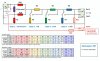
Hi John. Looking at the footswitch diagram....I'm confused as to why a stereo jack is used and not mono switched jack?

Thanks!
 

Gene Ballzz

Well-Known Member
Joined
Feb 19, 2013
Messages
4,697
Reaction score
6,521
Location
Las Vegas, NV
@matttornado
Although there may be an instance or two (in this very lengthy thread) that actually use the ring for switching, @JohnH described early on that he likes the "stereo" jacks for the extra sturdiness and support they provide Even when the ring terminals are not connected to anything. Please remind me what post number range includes pics of your build?

Ain't this attenuator design just the greatest thing since sliced bread? :naughty:

Quieter In Oh Wellia,
Gene
 

matttornado

Well-Known Member
Joined
Mar 14, 2012
Messages
1,900
Reaction score
1,510
@matttornado
Although there may be an instance or two (in this very lengthy thread) that actually use the ring for switching, @JohnH described early on that he likes the "stereo" jacks for the extra sturdiness and support they provide Even when the ring terminals are not connected to anything. Please remind me what post number range includes pics of your build?

Ain't this attenuator design just the greatest thing since sliced bread? :naughty:

Quieter In Oh Wellia,
Gene
It sure is, Gene! This attenuator is coolest and best thing I ever built.
 

matttornado

Well-Known Member
Joined
Mar 14, 2012
Messages
1,900
Reaction score
1,510
@matttornado
Although there may be an instance or two (in this very lengthy thread) that actually use the ring for switching, @JohnH described early on that he likes the "stereo" jacks for the extra sturdiness and support they provide Even when the ring terminals are not connected to anything. Please remind me what post number range includes pics of your build?

Ain't this attenuator design just the greatest thing since sliced bread? :naughty:

Quieter In Oh Wellia,
Gene

I start chiming in with questions on page 20 & then start posting pics of my build on page 28. I'm slow builder though. lol
 

matttornado

Well-Known Member
Joined
Mar 14, 2012
Messages
1,900
Reaction score
1,510
So the ring and tip are tied together at the attenuator's FS stereo switched jack but separated at the footswitch's stereo jack?
 

donwagar

Well-Known Member
Joined
Nov 24, 2018
Messages
254
Reaction score
694
Location
Calgary, Alberta
So the ring and tip are tied together at the attenuator's FS stereo switched jack but separated at the footswitch's stereo jack?

Yes, when the plug is out at the attenuator, the ring and tip then connect via the switched terminals. Then the attenuator can work without the footswitch.
 

ThePanda

New Member
Joined
Jan 19, 2021
Messages
13
Reaction score
10
Can someone check my work. Adding 5k pot and resistor for the line out.
 

Attachments

  • 20210922_173858.jpg
    20210922_173858.jpg
    271.3 KB · Views: 26

JohnH

Well-Known Member
Joined
May 31, 2008
Messages
6,155
Reaction score
5,062
Location
Wilton NSW
The ring terminal and switch contacts are used at the footswitch jack at the main box because there are three wires that need connecting, being cold, and each side of the hot being output from the amp, and also onward to the speaker. Diagram soon...

The other place I use the ring terminal is for Out 3 on the 8 ohm designs.
 

JohnH

Well-Known Member
Joined
May 31, 2008
Messages
6,155
Reaction score
5,062
Location
Wilton NSW
Here's a new version of the footswitched diagram, coloured to show how the jack is hooked up. In the inset picture, the main contacts are on the far side. The pink and red wires cross over , and youd wire them underneath but I showed it over the top to make it clear

 
Last edited:

JohnH

Well-Known Member
Joined
May 31, 2008
Messages
6,155
Reaction score
5,062
Location
Wilton NSW
Can someone check my work. Adding 5k pot and resistor for the line out.

This looks ok. See how it goes, the best values may depend on how loud the amp is and what you are driving the line-out into. If you need more output level, the 470 could increase to 1k or 2.2k
 

matttornado

Well-Known Member
Joined
Mar 14, 2012
Messages
1,900
Reaction score
1,510
excellent! thanks for clearing that up and making a new chart. that diagram alone is priceless!!!!!
 

Graham G

Well-Known Member
Joined
Feb 4, 2018
Messages
252
Reaction score
359
Hi @Graham G , hot melting glue may not be the best, since it could melt it it gets hot. A dab of silicone would be better, or zip ties. or a non steel bolt

Thanks i'll avoid the the Hot Melt :), the last of my parts should be arriving Today, this may be already in the thread but I've missed it, but are there any meter measurements/tests I can do to check I have the circuit & switch wiring correct ?.
 

JohnH

Well-Known Member
Joined
May 31, 2008
Messages
6,155
Reaction score
5,062
Location
Wilton NSW
Yes, and I id advise that too!

Best test is to check resistance seen by the amp. Plug speaker into attenuator, and a cable into the input, but no amp. Measure resistance across thd input cable in every switch setting. For the 8 Ohm build, it should be between about 7 and 10 ohms in every setting. x2 for the 16 ohm ones.
 

Graham G

Well-Known Member
Joined
Feb 4, 2018
Messages
252
Reaction score
359
Thanks John, will do, the switches (On -On) are going to be the last items to arrive, so i'll see if I can figure out the contacts wiring before I start asking for help :D.
 

matttornado

Well-Known Member
Joined
Mar 14, 2012
Messages
1,900
Reaction score
1,510
This was the diagram:


The signal does go out to the footswitch and back, via a special 3-core cable made using 5A mains flex and stereo jacks. But It's not the whole current, it's already attenuated. For a typical 50W 8ohm build, it's about 1.1A max. On the footswitch, two of the three poles are used in parallel to get plenty of current rating. And a typical 3pdt such as you build into a stomp box, has a rating of 4A at 125V per contact anyway.

If the footswitch is not plugged in, then the switched jacks sends the signal through to the speaker

I think this idea is ok provided the first reactive stage is always on, so not using it for a full bypass.

can a 3 prong A/C extension cord be used?
Footswitch -3.5dB Stage

full


Someone on one of the SV20 threads mentioned it might be good to have a footswitchable attenuator to cut just the volume (without losing tone). I thought that was a brilliant idea. An easy way to go from rhythm to solo volumes.

I was just starting to plan to build an M2, so I asked JohnH if it was possible. He already had a schematic for it.

I finally finished it, it works great. (I still have to collect the parts and add an LED to it).

Because the SV20 already has a 5W switch, and because I'm not planning on using it at home (I keep it in our practice space, only use it for practices and gigs), I left the -14dB Stage out of mine.

So it has -7 (reactive), -7 and -3.5 switchable, and -3.5 on the footswitch. My amp is the SV20C combo, so one speaker, so I only used one speaker jack.

I think this attenuator is fantastic, anyone that is reasonably handy really should build one.

[Gene noticed the original jacks I used weren't isolated, thanks for that, fixed now]
where did you get your cable for the footswitch? that’s all i need and then i’ll be ready to build.
thanks!
 

JohnH

Well-Known Member
Joined
May 31, 2008
Messages
6,155
Reaction score
5,062
Location
Wilton NSW
can a 3 prong A/C extension cord be used?

where did you get your cable for the footswitch? that’s all i need and then i’ll be ready to build.
thanks!

In principle, yes that's fine as a cable type, you get three reasonably thick stranded cores in a non-screened cable, equivalent to a speaker cable with an extra core. The main issue is its thick enough, but not to get one too thick that it cant squeeze into a jack plug barrel (you still need to use a jack socket and plug). I've got some three-core 5A flex and that's what Id use if I built this myself.
 

donwagar

Well-Known Member
Joined
Nov 24, 2018
Messages
254
Reaction score
694
Location
Calgary, Alberta
Last edited:
As an Amazon Associate we earn from qualifying purchases.

Graham G

Well-Known Member
Joined
Feb 4, 2018
Messages
252
Reaction score
359
As I suspected i'm struggling with working out the switch :(,
the switch I have ordered is a DP On-On with 2 rows of contacts, top & bottom contacts labelled On On with no label on Centre contact, see pic below.
I have no pin continuity with the toggle up(or off) but with the Toggle in the down(or on)I do have continuity between Top(on) pin & the centre the centre pin, but I have no continuity with the Bottom (on) pin in any toggle position, i'm a bit lost, I'm not sure in Johns original drawing(which I copied in my Hand sketch) which are the On-On ar centre pins as per my switch.
Or do I have the wrong type of switch ?
Cheers, Graham.

d0ek9vL.jpg
 

JohnH

Well-Known Member
Joined
May 31, 2008
Messages
6,155
Reaction score
5,062
Location
Wilton NSW
It's a good idea that you are testing the switches with a meter set to ohms

So the lugs are in a 2x3 pattern. Arranging that pattern vertically, so that the lever flicks up and down, then use just one side ie one group of three. Labelled 1, 2, 3 as you sketched, we expect as follows:

Lever Up: 2 is connected to 3, 1 is disconnected
Lever down: 2 is connected to 1, 3 is disconnected

Ie, usually, Lever up makes the middle lug connect to the lowest lug.

All of that applies to the left and to the right sets of three. You can ignore say, the left three, since we only use one pole.

Does that work?
 

Graham G

Well-Known Member
Joined
Feb 4, 2018
Messages
252
Reaction score
359
John, once again thanks for your time & help, yes on a continuity test the switch works as you have said, my issue is I can't work out which wire connects to which lug.
If I take the First switch I have the following wires to connect, if i'm reading your diagram correctly,i.e.
1 wire from front of Resistor 4(or rear of 2A) to Switch.
1 wire from rear of Resistor 4 to Switch.
1 wire from top of Resistor 3 to Switch.
I can't work out which wire goes to which Lug of the switch, I can follow it fine on your diagram but the lugs are in a different pattern, I know i'm not quite technical enough to understand how the circuit works, but i'm ok doing the work.

Edited to add, i'm trying to figure this out & I've come up with this, using Switch 1 as an example.
Front of Resistor 4 to Centre lug.
Rear of Resistor 4 to Bottom lug.
Front of resistor 3 to Top lug.
Anywhere near ? :rolleyes:.
 
Last edited:

Latest posts


Top