JohnH
Well-Known Member
Hi @kaludjerko , and thanks for your interest.
The values are not super-critical, and I doubt you'd hear a difference across those values of L2.. Can you find the specified value for L1?
But, to make a choice: A higher L2, if you could hear a diffference, would theoretically be slightly brighter, and a bit more 'lively'. I'd go with the higher value of 0.56mH assuming L1 is as designed.
But its a good question. Ill run the numbers to let you know what difference it really would make.
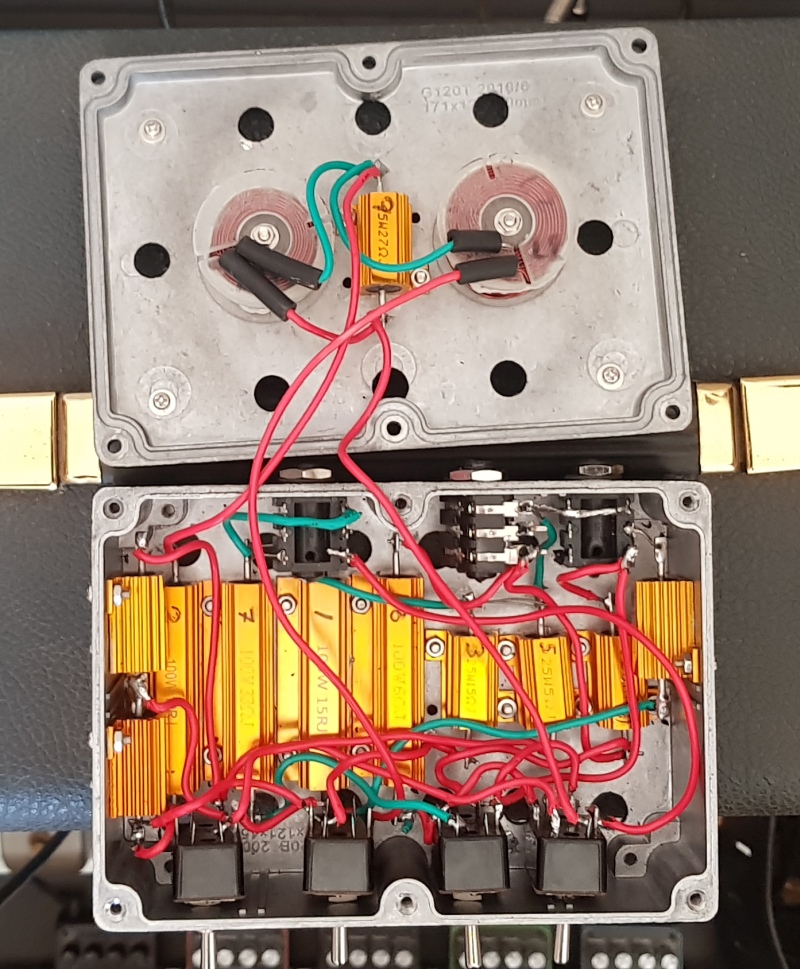
Actually, if needed, you can reduce inductance by unwinding a few turns and re-taping the coil. Ive done that to make mine, but I have an inductance range on my meter to help do it.
And, you can also increase inductance by mounting a small steel bolt on the central axis of the coil.
The values are not super-critical, and I doubt you'd hear a difference across those values of L2.. Can you find the specified value for L1?
But, to make a choice: A higher L2, if you could hear a diffference, would theoretically be slightly brighter, and a bit more 'lively'. I'd go with the higher value of 0.56mH assuming L1 is as designed.
But its a good question. Ill run the numbers to let you know what difference it really would make.
Actually, if needed, you can reduce inductance by unwinding a few turns and re-taping the coil. Ive done that to make mine, but I have an inductance range on my meter to help do it.
And, you can also increase inductance by mounting a small steel bolt on the central axis of the coil.
Last edited:


 in here!