JohnH
Well-Known Member
Hi @Yamariv
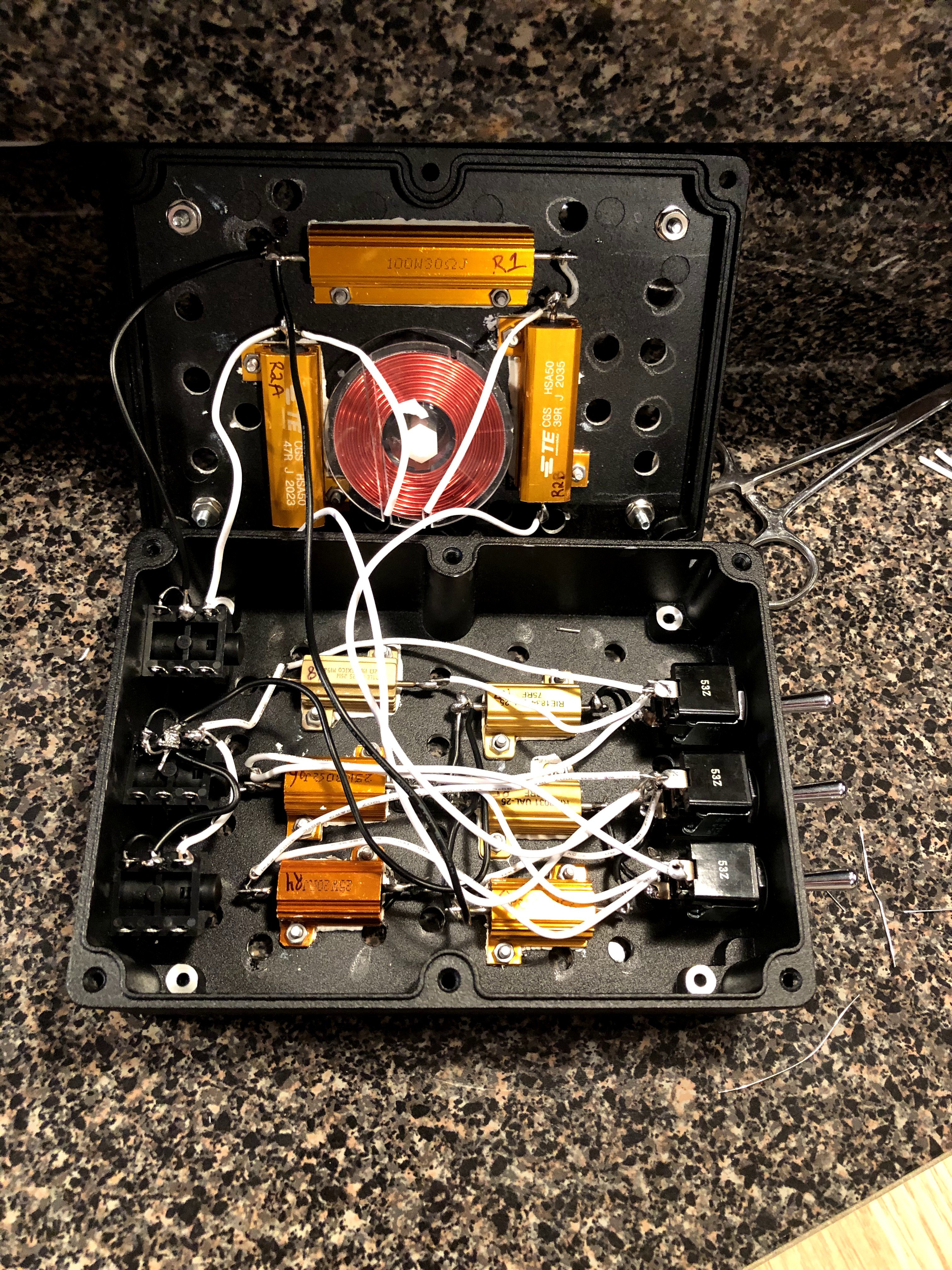
its really a good idea if you work out the wiring yourself on a sketch, taking into account the size of the parts and the case that you have. Then you will have thought it through and have something to work off.
Every layout built so far has needed to be a bit different and all builds that I know of have been a success. I haven't wanted to post a wiring layout because then it becomes possible to try to build these without thinking it through and hence mistakes could be made. Interpreting the schematic into a wiring layout is the entry exam for using the design!
When working out a physical layout related to the schematic, in this case, it doesn't matter how the wiring goes so long as the correct lugs are connected. eg A to B to C is the same as B to A to C or A, B and C all to one point etc. (not true in an amp but perfectly ok here)
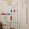
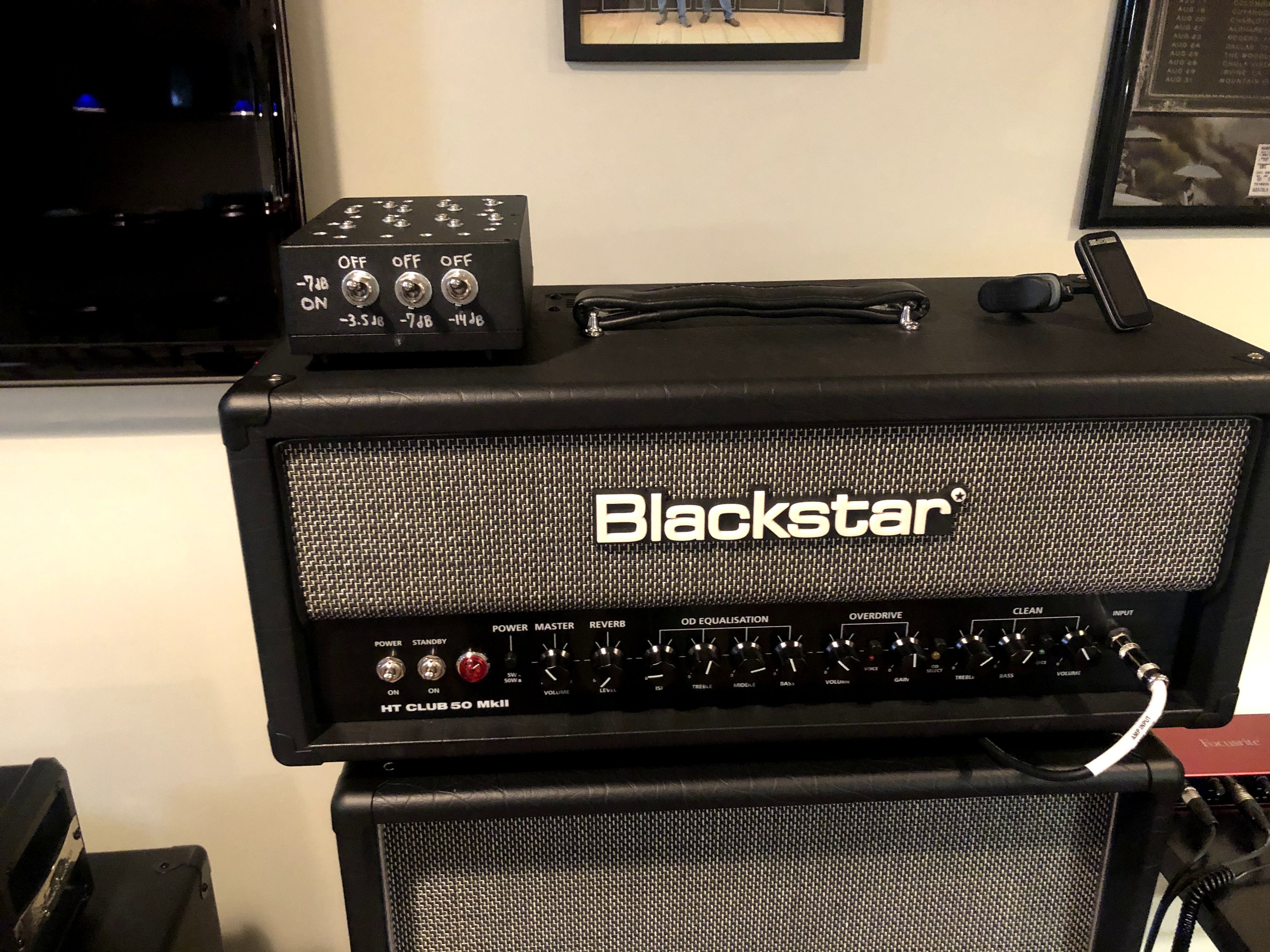
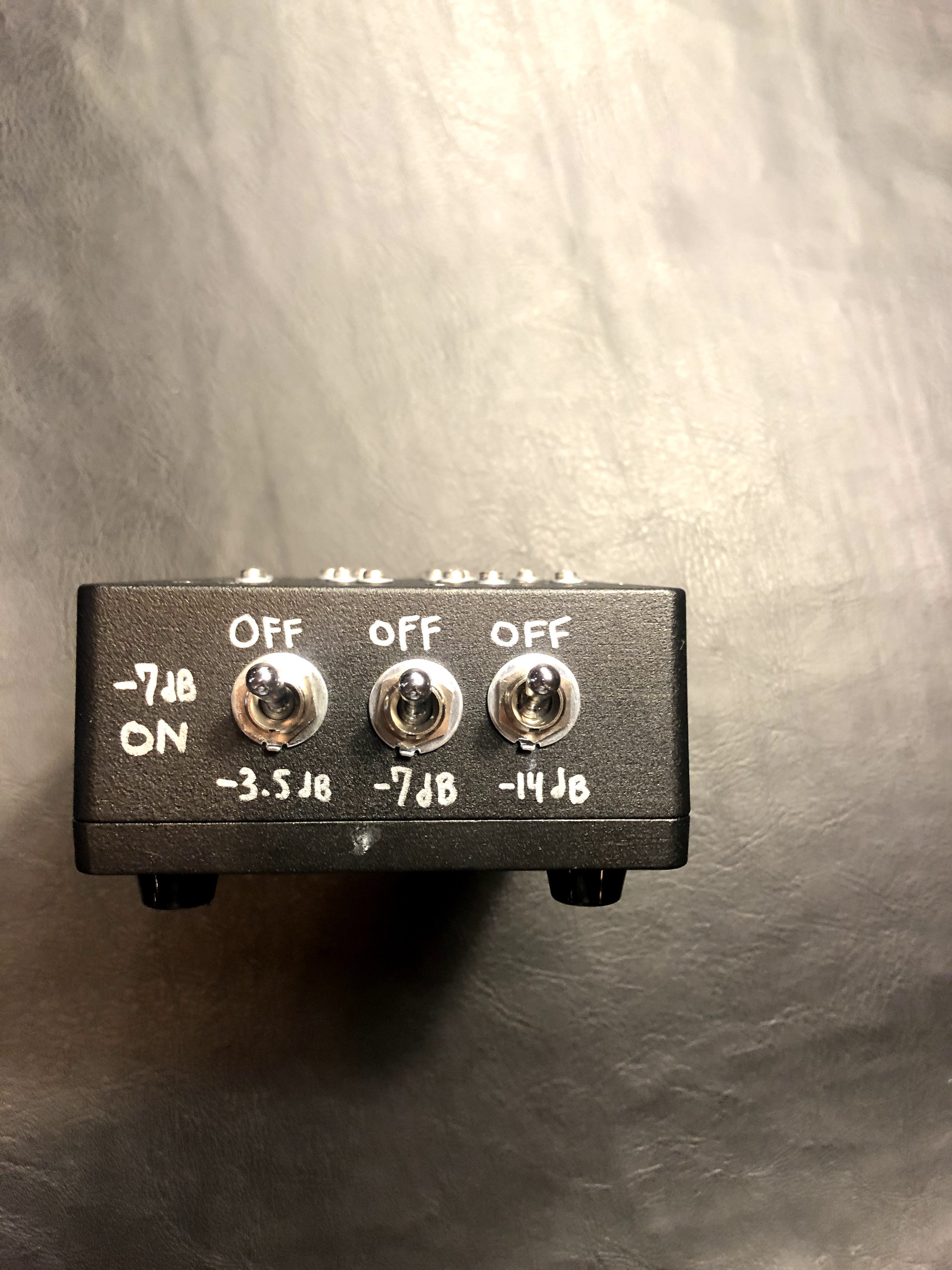
On the schematic, the switched stages are shown -7, -14 then -3.5, for a small electrical reason. You can follow that in terms of wire connections but physically, you probably want to place the switches 14, 7, 3.5 or 3.5, 7, 14
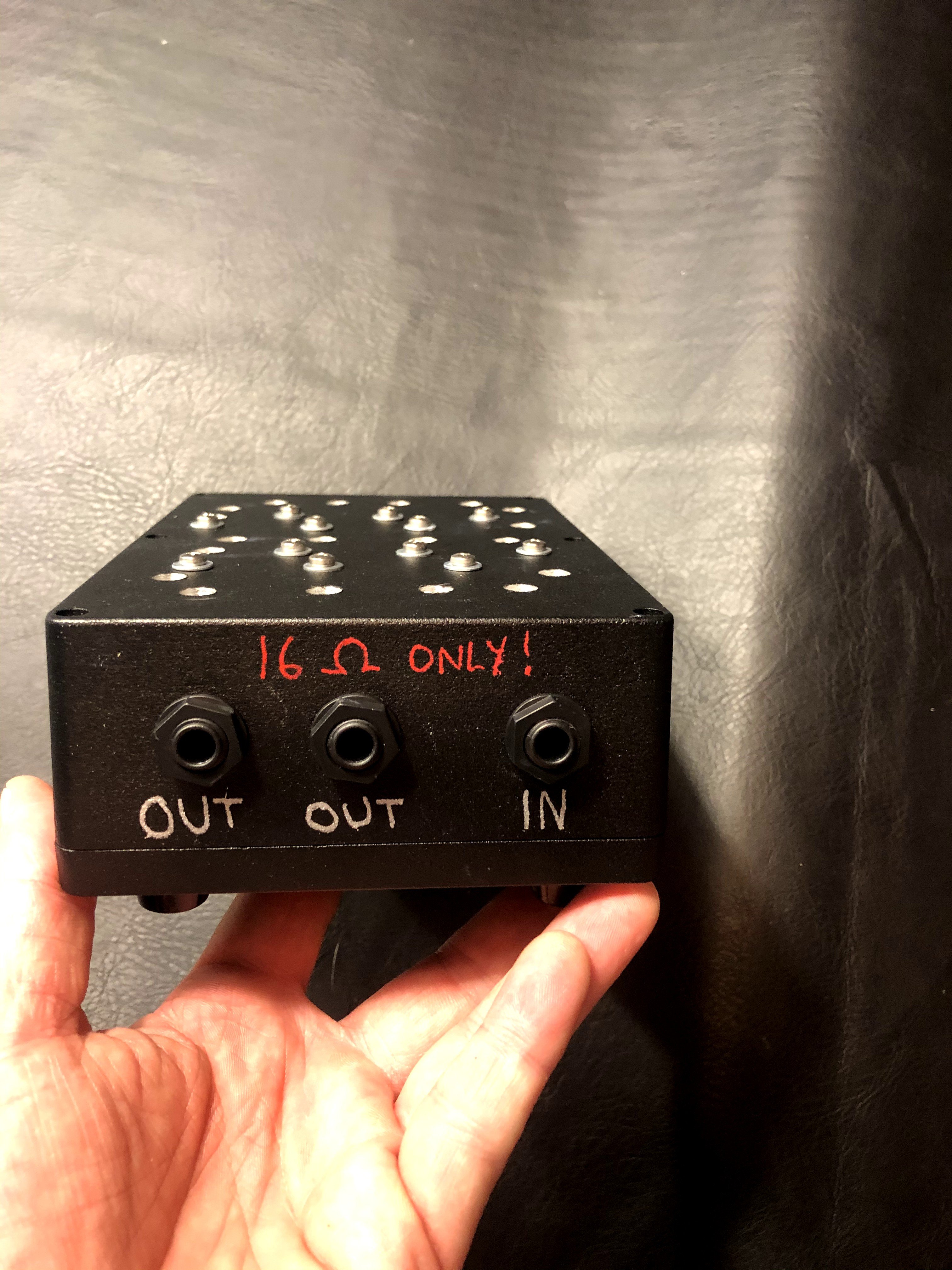
Think about how to place the jacks and switches in your case, so that it operates conveniently in your rig.
Try to minimise lengths of wire runs where possible
Think about the order of wiring and how you will work on it and open and close the case
The case should not be connected to anything.
When its built, test it with a resistance setting of a multimeter before using an amp
its really a good idea if you work out the wiring yourself on a sketch, taking into account the size of the parts and the case that you have. Then you will have thought it through and have something to work off.
Every layout built so far has needed to be a bit different and all builds that I know of have been a success. I haven't wanted to post a wiring layout because then it becomes possible to try to build these without thinking it through and hence mistakes could be made. Interpreting the schematic into a wiring layout is the entry exam for using the design!
When working out a physical layout related to the schematic, in this case, it doesn't matter how the wiring goes so long as the correct lugs are connected. eg A to B to C is the same as B to A to C or A, B and C all to one point etc. (not true in an amp but perfectly ok here)
On the schematic, the switched stages are shown -7, -14 then -3.5, for a small electrical reason. You can follow that in terms of wire connections but physically, you probably want to place the switches 14, 7, 3.5 or 3.5, 7, 14
Think about how to place the jacks and switches in your case, so that it operates conveniently in your rig.
Try to minimise lengths of wire runs where possible
Think about the order of wiring and how you will work on it and open and close the case
The case should not be connected to anything.
When its built, test it with a resistance setting of a multimeter before using an amp

 )
)
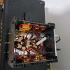
 So now to decide from all those options, I might just do some silicone adhesive right to the case.. Thanks again John, gonna start building soon
")
