• We are looking to make improvements to the Classifieds! Help us determine what improvements we can make by filling out this classifieds survey. Your feedback is very appreciated and helpful!

    Take survey

Simple Attenuators - Design And Testing

  • Thread starter JohnH
  • Start date
  • This site may earn a commission from merchant affiliate links like Ebay, Amazon, and others.

Graham G

Well-Known Member
Joined
Feb 4, 2018
Messages
252
Reaction score
359
Hi Graham, all good, it seems to be fine then. Do you think this -3db work-round will be helpful overall?

On heat, i think the way these work is more dependent on power than is the actual volume - different physics at play. For example consider 25W (a cranked SV20?), 50W and 100W. There's only a 3db step between each one, which is a small step of volume. But on temperatures, in a thick case, 25W gets warm, 50W can get hot if you thrash continuously but not excessively so, and 100W can get way hot and a fan may be needed. Also, it takes quite a while for the temperature to change as it heats up the case, so the power that heats it up is averaged over maybe 30 minutes.

Hi John, based on yesterdays brief practice session, I think it will be exactly what I need forJ my pub gigs, but i'm at the Merseycats Jam night Tonight(which will be a good test & then Friday we're doing an actual gig so by Saturday i'll have a really good idea if the fixed Stage solution is all I need, right now I think it will be.
I'm thinking of making it a permanent fixture in the back of my Amp, the case I've used is a tiny bit too deep, but I think i'll be able to coax it in there with a big hammer :D.
I'm also thinking about "hard wiring" inside instead of the y shaped lead, so could I ask a couple of questions ?
My reading of the box I've built now is i'm not using the switching(permanently on) & i'm not using the original speaker out Jack, so could I hard wire the circuit in the following way ?
wire resistors 3-5-7 to 4-6-8 ?, it looks to me like this would work to by pass the switches in the On position.
Also could I disconnect the leads from resistors 7-8 from the original speaker Jack(not now used) & then use the jack for my internal Y wiring ?.
I'll report back on Saturday after my gigs.:band:
Thanks John. How's the D button idea coming along ? :D.
 
Last edited:

JohnH

Well-Known Member
Joined
May 31, 2008
Messages
6,155
Reaction score
5,062
Location
Wilton NSW
ok great. Once you've concluded, you might be interested in putting together a simple, smaller, single box to do the same. Without all the attenuation settings, it can be distilled down to:

Output from amp 16ohms
standard speaker cable
box with one jack in, one jack out and three components (two resistors and a coil)
plug 8 ohm speaker into that.

Power is reduced -3db to 25W, as with the 3-way cable system.
 

Graham G

Well-Known Member
Joined
Feb 4, 2018
Messages
252
Reaction score
359
ok great. Once you've concluded, you might be interested in putting together a simple, smaller, single box to do the same. Without all the attenuation settings, it can be distilled down to:

Output from amp 16ohms
standard speaker cable
box with one jack in, one jack out and three components (two resistors and a coil)
plug 8 ohm speaker into that.

Power is reduced -3db to 25W, as with the 3-way cable system.

That sounds great, i'll report back on Saturday :)
 

matttornado

Well-Known Member
Joined
Mar 14, 2012
Messages
1,900
Reaction score
1,510
I added the switched stereo jack to the attenuator. Not as neat as I'd like but it was a tight squeeze. I am making the cord now.

pic3.jpg pic5.jpg
 

matttornado

Well-Known Member
Joined
Mar 14, 2012
Messages
1,900
Reaction score
1,510
I tried the footswitch addition yesterday for about a half hour and it worked great! I can't wait to use it at one of our gigs. I think the 3.5 db boost will be enough but I'll find out soon.

Thanks again @JohnH!
 

Graham G

Well-Known Member
Joined
Feb 4, 2018
Messages
252
Reaction score
359
I used the M2 on Thursday(jam night) & Friday nights(gig) running it with a wired fixed -3.5db reduction that John did me a drawing for & it sounded really Great the M2 keeps all dynamics & welly in tact at about half power.
My Amps a HF modded ORI50C & to be honest I just can't believe how good the combination of the Mod & the M2 sounds, the M2 allowed me to run the Gain & the Volume right in the sweet spot & it's the best on stage(pub band stage) sound I've had for years & I've had some very good & expensive Amps.
In an ideal world i'd like to have an M2 that could switch from this fixed state to go up & down by about 10w, but I think from Johns comments that's not possible, but sometimes you just can't have everything & so i'm really happy with this set up.
:band:
 

JohnH

Well-Known Member
Joined
May 31, 2008
Messages
6,155
Reaction score
5,062
Location
Wilton NSW
Following on from what Graham is finding, I think there are several ways to split the first step of attenuation, to have a built-in -3 or -3.5db setting. A new idea: This can include making the first stage switchable between -3.5 and -7. I'll post more on that.

There are also ways to make a fixed -3 or -3.5, using the M2 as a load box, or making a much stripped down fixed load.

But for most users, the basic M2 does what's needed and is simple and versatile.
 

JohnH

Well-Known Member
Joined
May 31, 2008
Messages
6,155
Reaction score
5,062
Location
Wilton NSW
I've worked out a way, with one more switch, to make the first reactive stage switchable between-7db as usual, and -3.5db. This means that when just a small reduction is needed, that step is available ie, 50W goes down to about 20W. The tone looks like it will be correct at -3.5 db. It'll be safe to switch other switches too from there, but slightly less 'reactive'. Best to start with -7db at stage 1 when lower settings are needed.
 

matttornado

Well-Known Member
Joined
Mar 14, 2012
Messages
1,900
Reaction score
1,510
I tried my 3.5 db footswitch the other night at an outside party we played. It worked very well. There were no delay when turning off the footswitch stage and the footswitch enclosure just got a little warm. I'm not sure if 3.5 db is enough of a volume boost or not for doing leads and solos. I think I need to try it a few more times, especially indoors before I can decide. Would 7db be too much of a volume boost?

Could there be a stage in between 3.5 & 7 db?
 

JohnH

Well-Known Member
Joined
May 31, 2008
Messages
6,155
Reaction score
5,062
Location
Wilton NSW
I tried my 3.5 db footswitch the other night at an outside party we played. It worked very well. There were no delay when turning off the footswitch stage and the footswitch enclosure just got a little warm. I'm not sure if 3.5 db is enough of a volume boost or not for doing leads and solos. I think I need to try it a few more times, especially indoors before I can decide. Would 7db be too much of a volume boost?

Could there be a stage in between 3.5 & 7 db?

Thats great news!
In principle, the footswitch stage can be any amount of dB's in the range. It's easy to work them out if you want an in between one.

Also, It would be possible to add another switch to the footswitch box to change the footswitch dB's.

But I'd suggest to experiment with the main box switches, particularly the -7 db switch, to help decide on values.
 

auflauf

New Member
Joined
Sep 27, 2021
Messages
11
Reaction score
10
Back again and I am completely blown away. Some nice person on this forum lend me a beautifully built M2. So I tried it and my results range from very good to quite ok. An attenuation of -7db sounds fine. -10db starts to sound a bit muddy, - 21db more so and so on. This is fine on its own right, attenuators are said to behave like this. The M2-design is most probably one of the better ones as it sounds quite nice for me down to -14db.

So I expected to find a loss of high frequencies with progressing attenuation. I checked the frequency response with a crude setup:
  1. Harley Benton Tube15, semi-open combo, back removed for better access to the wires, positioned arbitrarily on a shelf in a corner
  2. Behringer ECM8000 mearsurment microphone positioned in 1m distance in front of the speaker's center
  3. noname 15€ el-cheapo USB-interface
  4. REW Room Equalization Wizard 5.20.3
  5. output from USB-interface to amp input jack
  6. all curves are smoothened by 1/6oct
These are the results: the first image shows frequency response curves without and with a different amount of attenuation. What appears to be too good to be true: they are perfectly parallel to each other. This is exemplified in the second image: the curve of the frequency response measured with -10db has been added 10.5db in the software, the same has been performed for the -21db measurement. They fit perfectly well to the 0db-curve. The low frequencies appear to rise with more attenuation, but this results from the noise floor which is not affected by the attenuation and hence is relatively louder with more attenuation.


M2 on Harley Benton Tube15.jpg M2 onHBT15-0db_-10db_-21db_curves moved up.jpg

Thus, the attenuator works absolutely perfect. The audible result is good, but not perfect for me. I would like to add eg +5 to +7db to the heights. This might be due to Fletcher-Munson or to Robinson-Dadson, but the effect is so marked that I doubt that.

Reduced distortions and second/third harmonics with increasing attenuation might be the reason, in other words an amplifier-speaker-interaction. But I would have expected to see the loss of harmonics causing a loss of heights in the frequency sweep above.

Next I will look at the spectrum of a chord and if there is a loss of harmonics visible.

For now, I am deeply impressed by your attenuator and I have stuff to think about...
 
Last edited:

JohnH

Well-Known Member
Joined
May 31, 2008
Messages
6,155
Reaction score
5,062
Location
Wilton NSW
hi @auflauf , thankyou very much for these tests! Id like to check a couple of things about them:

Are these tests using a frequency sweep input? (ie not a guitar signal)
How hard was the amp working in terms of its output power?

Some comments:

The Tube15 amp has a 12" Celestion speaker, which generally all have about the same coil inductance, which is what the M and M2 designs are based on. So the parallel curves at each attenuation, from low-mids up are as expected
Even the -31db curve, is following the others well above about 300hz.

With different amps, Id expect some variation in the bass, since we do not include a bass resonance circuit in M2

On your traces, there's a bit of a peak around 80hz, which is usually the resonant frequency of a 12" speaker in an open cab

i find that the low attenuation settings sound fine to my ears if you start from a condition of quietness, but when you come down from high volume then they can sound more muted and dull. We could investigate how to lift the high frequencies if needed based on user preferences.

The curves are building up a bass increase at lower attenuations, apparently quite high as you get down to the lowest settings. We haven't seen this in the couple of tests done before. I wonder why? the Tube 15 is likely to have different output characteristics to my VM, which could explain, except that an such difference for that reason would be likely to occur between 0 and -7, and then stay fairly constant instead of building up increasingly at lower settings. As you noted above, it is maybe a noise-floor issue.

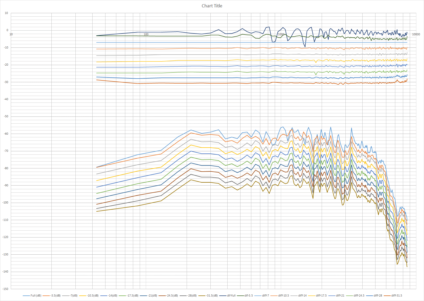
My own tests are posted in Post 1 with sound clips, here are the charts again:


I think the differences to yours are:
Its a looped guitar riff, at high power with distortion. The mic is placed close and its a dynamic vocal mic.
I made the comparisons by subtracting the trace at -7db from the others, hence to show ideally a flat line on each top trace for comparison
Its based on design M, which has a different front end but its electrical performance is almost identical to M2

Thanks again!
 
Last edited:

JohnH

Well-Known Member
Joined
May 31, 2008
Messages
6,155
Reaction score
5,062
Location
Wilton NSW
hi @auflauf , if you are doing some testing to look for harmonics, here are some things to watch and listen out for:

In principle, we expect the harmonic response to be quite close to the full unattenuated amp on account of the reactive coil, except possibly around the frequencies of the low bass speaker resonance. At this frequency, M2 does not show the amp an impedance that follows this, instead it remains flat. This may leave the bass with slightly less harmonics, or a different amplitude, if you play notes at high power around that frequency. In an open back 12" cab, we expect that around low E. Ive tried to find any such difference, exploring with Drop D tuning, but I cant hear them at all with my amp.

We have design M3 which includes a resonant circuit, that was built by @dbishopbliss, but there was not much difference noted. It would be very interesting to know your results on this using M2, for low bass notes and for higher frequencies, using your amp.
 

auflauf

New Member
Joined
Sep 27, 2021
Messages
11
Reaction score
10
Hi John! Thanks for your reply!
The volume setting was quite low and the amp definitely playing clean clean, thus no distortion coming from the amp.

The mic appears to be well suited for the job, published frequency response curves for it are really flat. 1 m distance is standard for speaker measurements, so this should be fine. The setup was crude, amp was not standing free, but as the bass was fine for me, I did not care.

The low frequency hump is definitely the noise floor. The USB sound interface is a 15€ piece of the size of a thumb drive. There are cables convoluted, humm etc. There are two pendulum clocks in the room with a half-second pendulum and a three-quarter pendulum. I don't know what the software makes of these peaks... maybe I repeat the measurement without them. Anyhow, a low frequency rise should not make the sound dull, thus I just disregard the bass.

Actually the otherwise fine REW-software only accepts frequency sweeps as output signals. I will have to tinker with one computer playing a recorded guitar chord and one computer do the recording with eg Audacity.

I definitely support the idea of including some kind of tone control to an attenuator. Ideal would be a high frequency rise adjustable in db and slope. The general "bad" reputation of attenuators appears to come solely from the perceived "dull" sound. this could be remedied by a beefy high boost of any sort.

Have to rush to work, Australia is preparing for end of work. Envious.
 
Last edited:

JohnH

Well-Known Member
Joined
May 31, 2008
Messages
6,155
Reaction score
5,062
Location
Wilton NSW
Thanks again

Lots of simple attenuators have a bypass cap to add treble. Generally, these are to compensate for dullness caused by an Lpad control damping the speaker, even though Fletcher Munson is blamed! As you've seen, this design does not have such a technical problem. But there could still be a user wish to boost treble. I'll look at it again. Need to be cautious though because adding the treble boost messes with impedances in a passive circuit like this.

btw, When I do these tests with guitar, I use a delay pedal set as a looper to make the input, then I mic into a mixer, then into Audacity
 

iefes

New Member
Joined
Apr 6, 2021
Messages
11
Reaction score
4
Really nice investigation auflauf, thanks for these tests! I'm glad you like my attenuator and I'm happy it does exactly what it is supposed to do. However, I'm wondering if you can really rule out that the low frequency increase at high attenuation levels (e.g., green line in the normalized graph) comes only from the noise floor. An increase around 200 Hz could make the amp sound more bassy and drown the high frequency content, thus make it sound duller. That's just an idea though.

It's cool how your test shows that a perfect attenuator is not always the perfect thing soundwise. Apparently, it highly depends on the amp + speaker being used and on your own preferences. Did you try to position the amp at different places and listening to it from different angles while playing? I don't know how different speakers behave at different volume levels but I can imagine that different speakers distribute the sound "unevenly" depending on the loudness.

However, I think these are great tests and these show really nicely that the attenuator is almost perfect on its own, but may be even improved in flexibility by adding some kind of a treble-bleed.
Actually, some attenuation in treble is caused by the inductance and the corresponding rise in impedance at high frequencies. Couldn't we just use a switch-resistor network to bypass the inductor partly, so it contributes less to the impedance curve? In this way no capacitors would be needed.

I might test this in LTSpice when I have time. But I bet JohnH will be faster :D
 

JohnH

Well-Known Member
Joined
May 31, 2008
Messages
6,155
Reaction score
5,062
Location
Wilton NSW
Actually, the inductor doesn't really control the tone, that is mainly determined by the resistor network The inductor controls the dynamics, how it responds to different input levels, and also adjusts to different amps.

If you short out the inductor completely then the result is a resistive attenuator, pretty much exactly the same as on page 4 ,3 years ago

The M2 design is set to try to minimise differences in tone at different attenuation levels.

I agree wuth @auflauf about the bass results.

Ive also run a few more calculated tests. If a treble lift is desired, i think it is safe to try a capacitor across R2A It needs to be bipolar, with high current capacity, like a crossover capacitor in a speaker. 10 uF (in an 8 ohm M2) gives a few db lift in treble. 3uF adds just a bit of extra presence. Try with caution, not tested yet I wouldn't use more than 10uF because it affects input impedance at high frequency
 
Last edited:

dbishopbliss

New Member
Joined
May 24, 2021
Messages
26
Reaction score
11
hi @auflauf ,
We have design M3 which includes a resonant circuit, that was built by @dbishopbliss, but there was not much difference noted. It would be very interesting to know your results on this using M2, for low bass notes and for higher frequencies, using your amp.
Let me know if you want to measure my M3. I have a gig that I need it for in 2 weeks but after that I could send it to you as long as you promise to send it back.
 

auflauf

New Member
Joined
Sep 27, 2021
Messages
11
Reaction score
10
An update and I am even more confused.
First, the noise floor. No input at the amp, gain 2, vol1. This is in concordance with the previous results showing a relative increase in lows with lower sound levels
Noise_floor 2021-10-12 um 19.13.11.png

Then an B7 chord played clean, recorded directly into the usb soundcard, spectrum analysis with audacity. No amp involved here:Spectrum H7 B7 clean 2021-10-12 um 19.34.22.png

Here is the recording of the amp playing the input of above file, no attenuation:
H7 clean 0db 2021-10-12 um 20.01.39.png

And here the spectrum of the recording of the attenuated amp
H7 clean -20db 2021-10-12 um 19.58.00.png

There is something missing ... this reflects the sound impression: dull

And here white noise played over the amp, no attenuation:
white noise 0db 2021-10-12 um 20.11.15.png

White noise played over the amp with -20db:
white noise -20db 2021-10-12 um 20.14.57.png

Conclusion:
1. There is a loss of heights with attenuation visible at the second, fourth and so on harmonics of the clean chord and at the white noise recording.

2. This is conform with the broad consensus of an attenuated amp sound.
3. This contradicts the measurements posted 4th of oct above. They have been produced with a frequency sweep.
4. The frequency sweep results did not go well with my expectations.
5. Perhaps absolute sound level and thus the speaker behavior plays an important role. Measurement setup was not very constant, calibrated etc. Overall level was rather low.

So, anyone with a brilliant explanation, please step forward.
 
Last edited:

JohnH

Well-Known Member
Joined
May 31, 2008
Messages
6,155
Reaction score
5,062
Location
Wilton NSW
I think its actually working fine. When you look at plots from a music signal, you just have to look at the peaks, everything else is noise.

Here is a copy of the full volume signal at the top and the -21db reduction below. I traced a dark blue line to join the peaks at the top, and also two horizontal lines 20 db apart. On the lower picture, I did the same in red. Then I brought the group of red lines up to the top chart, and adjusted by stretching vertically so the db scales were the same. You can see that the lines are quite close, and it was done roughly.

Above about 3khz, the trace is below the level of the recording of the attenuated plot.

auflaufoverlay211013b.gif
 
Last edited:

Latest posts


Top