• We are looking to make improvements to the Classifieds! Help us determine what improvements we can make by filling out this classifieds survey. Your feedback is very appreciated and helpful!

    Take survey

1965 JTM45 with EL34s: Dropping Resistors?

  • Thread starter Trouserpress
  • Start date
  • This site may earn a commission from merchant affiliate links like Ebay, Amazon, and others.

Trouserpress

Member
Joined
Apr 14, 2024
Messages
41
Reaction score
55
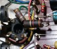
I'm looking at a picture of a most original JTM45 that's running on EL34s - but those aren't really a good match for the old RS transformers, right?. Between V4 and the board you can see 3 grey components (most likely resistors?) that might probably have been put in to take some high voltage stress off of the power tubes.
drop1.jpg
I'm no engineer and not quite sure if that would be a proper arrangement. Please take a look and tell me what you think. Thanks,
Frank
 

Creach

Member
Joined
May 20, 2023
Messages
79
Reaction score
68
I'm looking at a picture of a most original JTM45 that's running on EL34s - but those aren't really a good match for the old RS transformers, right?. Between V4 and the board you can see 3 grey components (most likely resistors?) that might probably have been put in to take some high voltage stress off of the power tubes.
View attachment 158666
I'm no engineer and not quite sure if that would be a proper arrangement. Please take a look and tell me what you think. Thanks,
Frank
Hello Frank,
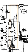
It should be a 1K resistor going to V4, and from this 1K a 470R on V4 and a 470R on V5.
On your picture the 1K resistor was replaced by the grey resistors and the 2 x 470R was replaced by a wire.
Here is a schematic and a picture of a JTM45 (with kt66) from 1965 that i saw a few years ago.
 

Attachments

  • Screenshot_20241005_022637.jpg
    Screenshot_20241005_022637.jpg
    304.3 KB · Views: 8
  • Screenshot_20241005_022842.jpg
    Screenshot_20241005_022842.jpg
    671 KB · Views: 6
Last edited:

Trouserpress

Member
Joined
Apr 14, 2024
Messages
41
Reaction score
55
Thanks Creach, so the original 1k(2w) in series with 2x 470R(1w) have been replaced by 3 assumably sturdier grey resistors and 2 leads. I wonder what value these might be and if that’s really all you have to do to complete a KT66 to EL34 conversion….???
I would have to buy it to get some more information (I‘m interested in doing so).
 

Creach

Member
Joined
May 20, 2023
Messages
79
Reaction score
68
Thanks Creach, so the original 1k(2w) in series with 2x 470R(1w) have been replaced by 3 assumably sturdier grey resistors and 2 leads. I wonder what value these might be and if that’s really all you have to do to complete a KT66 to EL34 conversion….???
I would have to buy it to get some more information (I‘m interested in doing so).
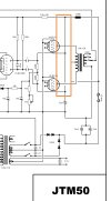
Right after the JTM45 is the JTM50 with el34.
The difference is JTM 50 has no resistor at all.
But for el34 a 1K can be placed instead of the 470R (and no need to have the first commun 1K).
 

Attachments

  • Screenshot_20241005_112822.jpg
    Screenshot_20241005_112822.jpg
    218.9 KB · Views: 4

Helmholtz

Member
Joined
Jul 20, 2024
Messages
19
Reaction score
25
I'm looking at a picture of a most original JTM45 that's running on EL34s - but those aren't really a good match for the old RS transformers, right?.
View attachment 158666
Judging from the OT wires this amp has a Drake OT.
Either a 784-103 (8k) for KT66s or a 784-128 (3.5k) for EL34s.
If intended for EL34s the bias supply should have a 220k series resistor.
 

Helmholtz

Member
Joined
Jul 20, 2024
Messages
19
Reaction score
25
Sorry, no.
Drake 103 and 128 have the same shape.
But it's obviously a Drake.
What are the secondary wire colors?
 

2L man

Well-Known Member
Joined
Sep 30, 2020
Messages
412
Reaction score
295
If options are those two the OT Winding Ratio/impedance is very easy to measure in few minutes. Remove power tubes and rectifier tube and there does not come HV to secondary circuit***. Then bend two wires to U and push between 2 and 3 on other power tube socket and between 7 and 3 on another. Then turn mains switch On and there come 50Hz or 60Hz sound from loudspeaker when filament AC go to OT primary thru Anode sockets. Disconnect loudspeaker and measure output AC voltage and AC between U-wires.

***Keeping HV/stby switch Off make that double safe and removing HV fuse make it triple safe.
 

Latest posts


Top