Trouserpress
Member
- Joined
- Apr 14, 2024
- Messages
- 42
- Reaction score
- 55
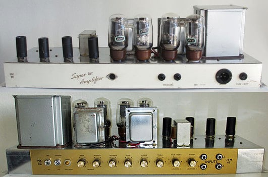
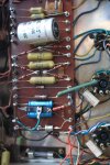
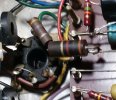
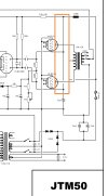
I'm looking at a picture of a most original JTM45 that's running on EL34s - but those aren't really a good match for the old RS transformers, right?. Between V4 and the board you can see 3 grey components (most likely resistors?) that might probably have been put in to take some high voltage stress off of the power tubes.

I'm no engineer and not quite sure if that would be a proper arrangement. Please take a look and tell me what you think. Thanks,
Frank
I'm no engineer and not quite sure if that would be a proper arrangement. Please take a look and tell me what you think. Thanks,
Frank

.jpg")