• We are looking to make improvements to the Classifieds! Help us determine what improvements we can make by filling out this classifieds survey. Your feedback is very appreciated and helpful!

    Take survey

Building a 5F6-A from the ashes of an old Italian PA amp

  • Thread starter pietro.castelli
  • Start date
  • This site may earn a commission from merchant affiliate links like Ebay, Amazon, and others.

pietro.castelli

Active Member
Joined
Aug 18, 2021
Messages
95
Reaction score
190
Hi Folks,
after my first tube amp build based on a Ceriatone kit - LINK - I've been growing the desire for a more challenging build, one that would start from scratch and allow me to study the behavior of a well-known circuit from the inside out. Fellow member @Marcomel79 has also been educating me on the art of repurposing and upcycling old tube devices.

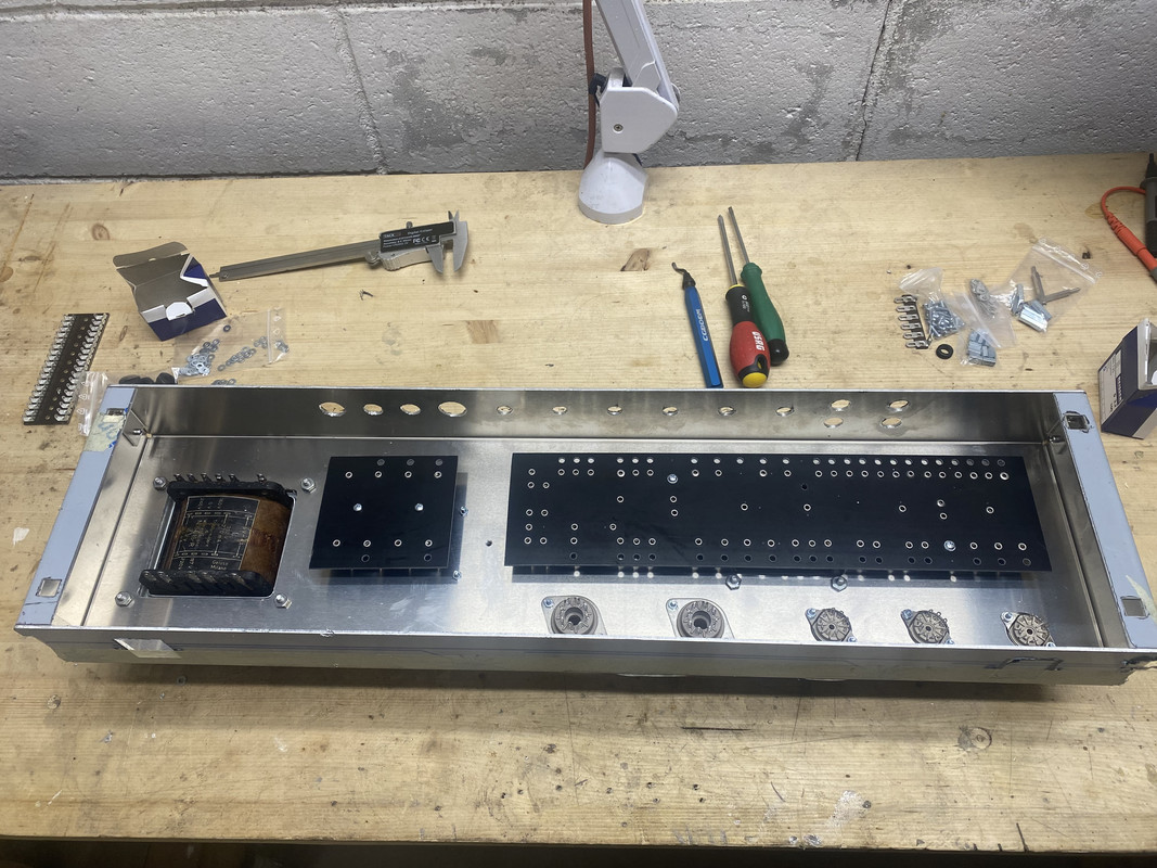
A few weeks ago, the perfect opportunity presented itself when I was gifted with the remains of an old Italian PA amplifier from my trusted luthier, a Geloso G1-1040/A from the late '60s that he has been stashing away for a conversion project that never happened.

It's a class AB, push-pull amplifier relying on a pair of EL34 for an estimated output of 40W.
It has a solid state rectifier and the preamp is made by 2XECC83 and an ECC81.

IMG_0750.JPEG

IMG_0754.JPEG


However it is missing all the tubes, the chassis is heavily oxidized and pitted, and the circuit has been butchered with questionable repairs and modifications:

rsz_img_0756.jpg
 

StingRay85

Well-Known Member
Joined
Aug 18, 2019
Messages
3,464
Reaction score
3,722
Just an FYI, in Belgium you find these Geloso amps for less than 50€ in perfect condition (but will need a cap job). Obviously in this case the tubes are gone. If I were you, junk this rust bucket, and look for a better amp to start from.
 

pietro.castelli

Active Member
Joined
Aug 18, 2021
Messages
95
Reaction score
190
I started by removing the transformers and preparing them for testing.
My OCD required a cleanup and a repaint:

IMG_0787.jpeg

The power transformer has primary windings for 117, 160, 220 and 240 Volts.
The secondary windings instead are rated for:

- 332V - 270 mA
- 6V - 4A
- 39.2V - 150mA

IMG_0788.jpeg

I started testing the transformer with a Variac and a light bulb current limiter:

IMG_0769.jpeg

With 228V on the 240V primary it reads:

- 270V on the 332V secondary
- 6.49V on the 6V secondary
- 35V on the 39.2V secondary

The HV secondary is a little weaker than expected but connected to a full bridge rectifier still gives a solid 465V DC output. I should still be able to have a healthy B+ when using it:

IMG_0809.jpeg
IMG_0810.jpeg
 

pietro.castelli

Active Member
Joined
Aug 18, 2021
Messages
95
Reaction score
190
Just an FYI, in Belgium you find these Geloso amps for less than 50€ in perfect condition (but will need a cap job). Obviously in this case the tubes are gone. If I were you, junk this rust bucket, and look for a better amp to start from.

I know they can be had for cheap but I had it for free.
The idea is to reuse the transformers only. There’s not going to be any rust at the end, trust me.
It would have definitely been easier to start with brand new parts, but I’m doing it on purpose as a learning experience.
 

StingRay85

Well-Known Member
Joined
Aug 18, 2019
Messages
3,464
Reaction score
3,722
They are cheap iron, that's for sure. The PT is the easy part, the OT will be a different story. It's hopelessly complex with all its impedance options.

But I'll be watching this topic with great interest. I was going to propose you to gift a complete G227A (excluding tubes), for the price of shipping.
 

pietro.castelli

Active Member
Joined
Aug 18, 2021
Messages
95
Reaction score
190
They are cheap iron, that's for sure. The PT is the easy part, the OT will be a different story. It's hopelessly complex with all its impedance options.

But I'll be watching this topic with great interest. I was going to propose you to gift a complete G227A (excluding tubes), for the price of shipping.

Thanks! I'll message you privately.
 

2L man

Well-Known Member
Joined
Sep 30, 2020
Messages
412
Reaction score
295
I don't see a filter capacitor on rectified voltage test and don't understand the voltage rise?

270VAC should come max 1.41 higher 380VDC after a bridge rectifier and filter capacitor.

Do not use LBL when you do actual tests. Variac is enough. Using LBL the actual feed voltage must be measured so that messures come true!

Feed 100VAC to OT primary and measure all outputs and then calculate winding ratios.
 
Last edited:

pietro.castelli

Active Member
Joined
Aug 18, 2021
Messages
95
Reaction score
190
I don't see a filter capacitor on rectified voltage test and don't understand the voltage rise?

270VAC should come max 1.41 higher 380VDC after a bridge rectifier and filter capacitor.

Do not use LBL when you do actual tests. Variac is enough. Using LBL the actual feed voltage must be measured so that messures come true!

Feed 100VAC to OT primary and measure all outputs and then calculate winding ratios.
To be honest I simply wired one of the bridge rectifiers that the amp came with, without any filter cap.
I know DC voltage is probably going down after filtering. I'll do some more tests as soon as I can.

P.s. I only used the LBL for the first startup, for all the voltage readings, the power transformer primary was wired directly to the mains power. I did use the variac to test the output transformer, you'll see it in my next post.

Cheers!
 

pietro.castelli

Active Member
Joined
Aug 18, 2021
Messages
95
Reaction score
190
The output transformer is a very strange animal.
It has three separate secondary windings with intermediate terminals that connected in series or parallel can match speaker impedances ranging from 1.25 to 500 OHMS.

rsz_11img_0789.jpg

I managed to find an old datasheet that lists 4000 OHMS of primary impedance, but I don't trust it, so I'll measure its impedance ratio, using this proven method from Uncle Doug:


This is the result of the measurement:

impedance ratio.png


It looks like the real primary impedance of this output transformer is about 2000 OHMS, but I can use impedance ratios and the many secondary windings' options to get 4, 8 and 16 OHMS speaker impedances at 3800 OHMS of primary impedance, which is what the RCA datasheet calls for 5881 tubes in push-pull configuration.
 
Last edited:

Marcomel79

Well-Known Member
Joined
May 3, 2021
Messages
1,822
Reaction score
2,675
Location
Oslo
Its fun to use what you have and figure out how to use it. Looking forward to seeing more of this project!
 
Last edited:

StingRay85

Well-Known Member
Joined
Aug 18, 2019
Messages
3,464
Reaction score
3,722
If you look at the back plate of the amp, it gives you the instructions how to wire up the OT, to get you the desired speaker impedance. The wire had to be soldered on the exterior, fully exposed.

See as an example: this can also guide you if needed, but of course voltage measurements are good enough. 3.8K is still good for EL34, after all it was designed for EL34...


geloso_G213_8g.jpg
 

pietro.castelli

Active Member
Joined
Aug 18, 2021
Messages
95
Reaction score
190
If you look at the back plate of the amp, it gives you the instructions how to wire up the OT, to get you the desired speaker impedance. The wire had to be soldered on the exterior, fully exposed.

See as an example: this can also guide you if needed, but of course voltage measurements are good enough. 3.8K is still good for EL34, after all it was designed for EL34...


View attachment 138787

That's actually what I used to start from and to do my measurements.
I needed to test that the output transformer was actually working and to measure its primary impedance, as I must use it with different tubes: 5881 vs EL34.
 

pietro.castelli

Active Member
Joined
Aug 18, 2021
Messages
95
Reaction score
190
After testing the transformers, it’s time to start the build.
Since I’m using reclaimed transformers, any standard premade chassis is not going to work for me.

I have two options:
- Modify the original chassis
- Build a new one from scratch

Initially, I tried to reuse the original chassis, but it was very oxidized and pitted, and it also had a weird layout with the circuit board mounted vertically. Finally, the metal alloy was really weird, and I struggled to weld it with the tools I had available.

I therefore decided to start from a fresh canvas and ordered a 100w Marshall-style chassis with no cutouts or holes from Tube Town.

I also ordered some fiberboard blanks to build some custom eyelet boards.
Once I received the raw materials, I started mocking up the amp layout, as well as drilling holes and creating cutouts for the transformers.

Using a pillow drill and an eyelets flaring tool, I also build the main circuit board as well as the capacitor board.

Here are some work-in-progress pictures:

IMG-0859.jpg


IMG-0868.jpg


Then a first test fit:

IMG-0887.jpg


IMG-0894.jpg
 
Last edited:

Marcomel79

Well-Known Member
Joined
May 3, 2021
Messages
1,822
Reaction score
2,675
Location
Oslo
Very nice Pietro! Its already looking like a beautiful build. Nice attention to detail as always
 

pietro.castelli

Active Member
Joined
Aug 18, 2021
Messages
95
Reaction score
190
This thread isn’t dead!
It has been months since my last update, but unfortunately my life in the last 12 months has become increasingly challenging. It’s not all negatives though, some challenges are definitely positive, but they mean way less time to dedicate to tube amps!

Anyway, I finally managed to finish at least the mechanical and assembly work on the chassis, which to be really honest, I don’t enjoy much.

It’s time to start with the electronics which I enjoy much more!

IMG-1579.jpg

IMG-1580.jpg


In addition to the main circuit board and the filter capacitors board, you can see two additional boards.
One is for HV and bias supply rectification. The second one is for the heaters virtual center tap and voltage dropping.

I’ve used a premade faceplate from tube town, while the backplate is built out of acrylic.
 

BlueX

Well-Known Member
Joined
May 5, 2020
Messages
2,703
Reaction score
5,676
Location
Sweden
This thread isn’t dead!
It has been months since my last update, but unfortunately my life in the last 12 months has become increasingly challenging. It’s not all negatives though, some challenges are definitely positive, but they mean way less time to dedicate to tube amps!

Anyway, I finally managed to finish at least the mechanical and assembly work on the chassis, which to be really honest, I don’t enjoy much.

It’s time to start with the electronics which I enjoy much more!

IMG-1579.jpg

IMG-1580.jpg


In addition to the main circuit board and the filter capacitors board, you can see two additional boards.
One is for HV and bias supply rectification. The second one is for the heaters virtual center tap and voltage dropping.

I’ve used a premade faceplate from tube town, while the backplate is built out of acrylic.
Looks very nice, especially since this not your favourite part. Really looking forward to what is your favourite. Also interesting to see your take on power board and heater CT.
 

pietro.castelli

Active Member
Joined
Aug 18, 2021
Messages
95
Reaction score
190
Looks very nice, especially since this not your favourite part. Really looking forward to what is your favourite. Also interesting to see your take on power board and heater CT.

Cant wait to see how it develops!!

Thanks for the encouragement, guys! I'll definitely try to keep a more regular pace now!
 
Last edited:

pietro.castelli

Active Member
Joined
Aug 18, 2021
Messages
95
Reaction score
190
The first task I wanted to tackle with the power supply section of the amp was the 6V heathers.
To start, the amp didn't have a physical center tap for the 6v secondary, and also, being built 60 years ago with contemporary AC mains, it was reading relatively high voltages.

I therefore decided to create a dedicated circuit board to build a virtual center tap and drop voltages using some antiparallel diodes, as suggested by the Valve Wizard here:

This is the end result:
unnamed-1.jpg

unnamed-4.jpg


I've used some big-ass 6A diodes for the antiparallel and some 100 ohms resistors for the virtual center tap.
I've also ordered some proper waxed lacing tape to tidy up the wiring, but it hasn't arrived yet, so I'll make it neater at a later stage.
 

Latest posts


Top