Barnsley Boy
Active Member
Some of these perhaps?
https://uk.farnell.com/sensata-airpax/67l040/thermostat-40deg-to-220/dp/2787344
https://uk.farnell.com/sensata-airpax/67l040/thermostat-40deg-to-220/dp/2787344
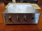
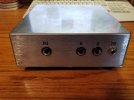
I got it from Aliexpress. Yeah, it cost as much as all my other parts combined, but I liked how it looked.I'm in love with that case Ace! Where did you get it from? Looks expensive.
Wow...excellent work, excellent work, all of you!! Thank you for sharing!
Hey Gene,^^^^^^^ What he said, times 10! ^^^^^^^
@Dblgun
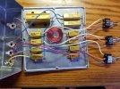
That's quite similar to what I'm planning for a future build! Simply GO-JUS! Looks like you followed my layout diagram, almost to the letter! A couple questions/comments:
A> Did you drill and tap the case for the resistor mounting screws?
B> How did you do the cutouts in the lid? Did you use a router, or simply a jig saw and file?
C> Depending on your amp wattage (and how hot the unit gets), you may want to consider drilling a few holes in the bottom, especially around the largest resistors for a bit of flow thru/convection cooling.
D> Pics of the bottom of both the lid and the unit would be nice to see?
Great Work All!
Gene


I have build 2, both in the cabinet. For both I added a by-pass switch, but in practice they are standard 'on' in the lowest setting.


That is a nice build. And down here at an outdoor gig in high summer, those 'brollies could be just the right thing. Otherwise in full sun, the box could collect more heat from solar radiation than from the amp power!@Mjh36 I love this!
The umbrellas look like an absolutely essential mod. If you could let @JohnH know the specification like fire rating (30/60/90 minute)
opening radius, which colour canopy gives the best cooling curve etc. I'm sure that he will upgrade the latest schematic to include
this!! I'm liking the lighting too. On a slightly more serious note and following on from temperature related switches, if you could work out a way
of lighting up the interior and switching the colours as the unit heats up, with red being danger level, that would be really cool (or hot!)
Good work fella,