A while ago I picked up a few Origin 20s and 50s with plans to convert them into turret board builds. After getting the OR20s I found Jason Tong's video on modding the OR20 and gave that a shot for fun. Jason detailed changing the stock circuit to a JCM 800 Jake E Lee spec. Nice little mod, but I already had other plans for the donor Origins.
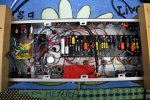
My goal was to use most of the stock amp parts to build an amp that can easily be modified and repaired in the future. The plan included using the head, chassis, transformers, tubes, switches and lamp, so all I would need is a turret board, pots, jacks, sockets and misc small parts.
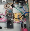
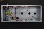
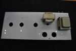
The chassis would need a few changes, like relocating the preamp sockets,enlarging the holes for the potentiometers and adding a few standoffs. All in all, not too much and I could retain the stock face plate.
Transformers could remain in their stock locations as could all the holes for pots, jacks, power tube sockets and switches.
I did opt for a Metropoulos loop on this build, unfortunately the jacks don't line up with the stock holes and perhaps on the next build I'll remote mount the loop board or go full tube loop.
The stock amp has a Tilt control, so many things you could do with that extra pot on an 800 circuit. I decided to go with a simple gain control after the second gain stage for more control of clean to overdrive. This stage would be great for a one knob tone like in a Big Muff with a few tweaks you could easily give it a mid boost or cut with a bass / treble tilt! Maybe on the next one.
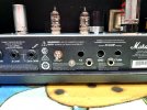
I've run this amp with the stock EL34s and 6V6s with a quick bias adjustment and both sound great.
*The stock power transformer has an offset center tap so just wire the center taps together (do not ground them) and use a bridge rectifier if you do this build.
With a bridge rectifer and no grounded center tap you'll need to use a Marshall 900 bias circuit.
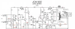
The preamp schematic is from Mark Huss with Jason Tongs noted Jake E Lee spec changes and was mostly adhered to, so thanks to those guys.
*The voltage on the schematic are not from the Origin, but I will update it someday.
*Any additional build info will also be added here.
As with any build, there's always something I'd do different in the next build, that's the fun of it!
Hope this post helps someone.
My goal was to use most of the stock amp parts to build an amp that can easily be modified and repaired in the future. The plan included using the head, chassis, transformers, tubes, switches and lamp, so all I would need is a turret board, pots, jacks, sockets and misc small parts.
The chassis would need a few changes, like relocating the preamp sockets,enlarging the holes for the potentiometers and adding a few standoffs. All in all, not too much and I could retain the stock face plate.
Transformers could remain in their stock locations as could all the holes for pots, jacks, power tube sockets and switches.
I did opt for a Metropoulos loop on this build, unfortunately the jacks don't line up with the stock holes and perhaps on the next build I'll remote mount the loop board or go full tube loop.
The stock amp has a Tilt control, so many things you could do with that extra pot on an 800 circuit. I decided to go with a simple gain control after the second gain stage for more control of clean to overdrive. This stage would be great for a one knob tone like in a Big Muff with a few tweaks you could easily give it a mid boost or cut with a bass / treble tilt! Maybe on the next one.
I've run this amp with the stock EL34s and 6V6s with a quick bias adjustment and both sound great.
*The stock power transformer has an offset center tap so just wire the center taps together (do not ground them) and use a bridge rectifier if you do this build.
With a bridge rectifer and no grounded center tap you'll need to use a Marshall 900 bias circuit.
The preamp schematic is from Mark Huss with Jason Tongs noted Jake E Lee spec changes and was mostly adhered to, so thanks to those guys.
*The voltage on the schematic are not from the Origin, but I will update it someday.
*Any additional build info will also be added here.
As with any build, there's always something I'd do different in the next build, that's the fun of it!
Hope this post helps someone.
Attachments

Last edited: