schematic request: tsl footswitch?

  • Thread starter scat7s
  • Start date
  • This site may earn a commission from merchant affiliate links like Ebay, Amazon, and others.

scat7s

Well-Known Member
VIP Member
Joined
Nov 19, 2010
Messages
13,862
Reaction score
7,292
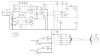
does anyone have one? from what i understand they used to be readily available, but arent any longer. i cant find one on the web.

my buddies tsl60 ftsw shit the bed, and the cable plug was re-worked with epoxy i was unable to get the pinout as they corrospond with the color codes.

thx
 

scat7s

Well-Known Member
VIP Member
Joined
Nov 19, 2010
Messages
13,862
Reaction score
7,292
i think ive found it, is this right?

p1-blk
p2-wht
p3-red
p4-yell
p5-grn
p6-blu
 

scat7s

Well-Known Member
VIP Member
Joined
Nov 19, 2010
Messages
13,862
Reaction score
7,292
for anyone in future who may need this, that IS indeed the correct pinout to wire color codes. got it working again last night.
 

RiverRatt

Well-Known Member
VIP Member
Joined
May 2, 2008
Messages
8,738
Reaction score
3,252
Location
Between Memphis and Nashville
I found this a few years ago and hung on to it just in case I ever needed it.

tsl100switchinginfo.gif
 

scat7s

Well-Known Member
VIP Member
Joined
Nov 19, 2010
Messages
13,862
Reaction score
7,292
nice, i have it scribbled on my schematic now, but im going to print and save this one. it looks nicer. thanks RR
 

Dega500

New Member
Joined
Jan 26, 2011
Messages
21
Reaction score
20
Location
Pinson, AL
Does anyone have a copy of the footswitch schematic they can upload or send me.

I am pretty sure I need to replace the clean and reverb switch in my TSL footswitch. Some part numbers for good replacements for those would be greatly appreciated.

Dega
 

scat7s

Well-Known Member
VIP Member
Joined
Nov 19, 2010
Messages
13,862
Reaction score
7,292
the clean is a momentary single pole single throw, i believe. the reverb is DPDT. circuit board mounted. these are standard footswitches, nothing unusual about them.

however since you think you need to replace both? i would question whether you have something else going on in there. those switches are pretty robust and to have two fail at the same time is somewhat unusual. most common failure is the harness/connector.

have you checked continuity of your cable yet? thats the first thing to do.
 

chuckharmonjr

In Memorandum
Joined
Mar 26, 2010
Messages
8,819
Reaction score
4,333
Location
About as far south in Alabama as you can go withou
Scat's absolute;ly right. Those switches are pretty much bulletproof but those cables have been a POS since Marshall first issued them. Theres been several folks on here re-wire the pedal and the head to a RJ45 jack and from then on just use standard computer CatV cables.
 

Dega500

New Member
Joined
Jan 26, 2011
Messages
21
Reaction score
20
Location
Pinson, AL
Thanks guys,

I did check the cable and removed a bad section of it near the footswicth end. Now, everything appears to working except the two suspect switches.

I did a little checking around with my multi-meter and although I'm not sure exactly which reading I should be getting, The Crunch and Lead switches (second and third from left) both went from a low resistance reading to full continuity when the button was held down and the clean switch did nothing when pressed. It feels slightly different to me also. The reverb switch hasn't worked at all, either before or after my attempt to repair the cable so I was just wanting to know a good replacement in case that became the problem.

I am also planning to replace the entire cable and maybe even ad a Din Connector to the chassis of the footswitch so cable replacement in the future will be easier.

Thanks for all your help so far,

Dega
 

Dega500

New Member
Joined
Jan 26, 2011
Messages
21
Reaction score
20
Location
Pinson, AL
"re-wire the pedal and the head to a RJ45 jack"

I've read that in a few places but have yet to find any details on actually how to go about it. The Pedal end seems doable but I'm afraid mounting an RJ45 Jack in the head might be a little beyond my comfort level. I've been inside tube amps before but mounting non-stock external jacks to PCB's sounds like it would require a carefully planned procedure to pull it off. Of course it may be simpler than I'm thinking it would be.

Thanks,

Dega
 

scat7s

Well-Known Member
VIP Member
Joined
Nov 19, 2010
Messages
13,862
Reaction score
7,292
ok, if you couldnt get continuity on the clean sw in the manner you described, it sounds like you might be on the right track with a replacement switch.

should be easy enough to prove out the reverb switch. the center tab will have continuity with one of the outside tabs (left or right) in one position, and the opposite outside tab when switched, this obviously applies to both rows of tabs. if you have anything different, then you may be right again. does that make sense? im not sure if i stated it clearly...and of course IN the cct, you may have continuity with other tabs as well depending on where the traces run, but you get the idea i hope?

if in doubt, you could remove it from the cct board to test.

i dont understand why those ftsw schematics arent available though...seems silly to withhold that but make their amplifer schematics freely available...
 

Dega500

New Member
Joined
Jan 26, 2011
Messages
21
Reaction score
20
Location
Pinson, AL
Thanks Scat7,

The effects switch is working. I may swap those out to check it. Of course I really don't think I'll be needing the reverb switch anyway, I may just leave it be for now.:hmm:
 

tall sg

Member
Joined
Feb 21, 2010
Messages
32
Reaction score
3
Location
S.New Jersey
This is the 5 button foot switch for the TSL diagram.

Hope this helps
 

Attachments

  • marshallfootswitch_Page_2a.jpg
    marshallfootswitch_Page_2a.jpg
    85.7 KB · Views: 398

scat7s

Well-Known Member
VIP Member
Joined
Nov 19, 2010
Messages
13,862
Reaction score
7,292
thats excellent, thx tallsg!
 

tall sg

Member
Joined
Feb 21, 2010
Messages
32
Reaction score
3
Location
S.New Jersey
Glad to help...only thing I noticed is C5 can't make out the value...someday will open it up and see what it is.
 

bobxjones

New Member
Joined
Jul 9, 2011
Messages
1
Reaction score
0
Hey Guys - Opened up the footswitch and C5 is a 1uf cap. Now onto the troubleshooting!

BTW, thanks Tallsg for the schamatic...
 

tall sg

Member
Joined
Feb 21, 2010
Messages
32
Reaction score
3
Location
S.New Jersey
Your all welcome...and c5 is now noted on my schematic...thanks bobxjones

next thing I want to do (just for looks mostly and really not sure why Marshall didn't do it) replace the 2 leds to a green and yellow.

the brain computes colors quicker than positions...and on a dark stage it is a no brainer for sure.

Tall SG
 

Morgan

New Member
Joined
Apr 11, 2012
Messages
18
Reaction score
2
Location
Knoxville, TN
First post - thanks in advance for any help. I'm fairly new at soldering my own stuff - so be warned I'm a knuckle head.

I've been working on my TSL footswitch. The cable went bad first. Replaced it with Cat 5. Later the Lead switch went out (it doesn't click any more when engaged nothing happens). So, I replaced it with a SPST switch, which I thought would work looking at the schematic Tall SG uploaded for us. Now, I've got channel switching as it should be, but the LEDs work sporadically. What type of switch is in the diagram? Looks like a SPDT, but the one leg goes no where. I don't get it.
 

scat7s

Well-Known Member
VIP Member
Joined
Nov 19, 2010
Messages
13,862
Reaction score
7,292
is your replacement sw a momentary sw?

it needs to be...that would account for the LED not working like it should.
 
Top