• We are looking to make improvements to the Classifieds! Help us determine what improvements we can make by filling out this classifieds survey. Your feedback is very appreciated and helpful!

    Take survey

Simple Attenuators - Design And Testing

  • Thread starter JohnH
  • Start date
  • This site may earn a commission from merchant affiliate links like Ebay, Amazon, and others.

JohnH

Well-Known Member
Joined
May 31, 2008
Messages
6,157
Reaction score
5,062
Location
Wilton NSW
16 ohm amp tap, 16 Ohm M2 and 8 ohm cab is totally safe, unless you have a bypass switch in it in which case the amp would obviously see your 8 ohm cab directly. If should also sound fine too, maybe a tiny tad brighter. So all fine really.
 

Paul Buxton

New Member
Joined
Oct 9, 2020
Messages
3
Reaction score
2
hi @Paul Buxton , welcome! you have found the right attenuator!

The 8 ohm M2 design is intended for using the 8 Ohm tap from your amp with either a single 8 ohm speaker cab, or two of 16 Ohms, hence its two parallel output sockets. Its also safe to use it with 8 ohm amp and a single 16 Ohm speaker, and if you build the optional red coloured parts in the diagram with the third output, it just corrects the tone for that arrangement.

What amp do you have?

Yes there's a lot of info and most of it is a journey rather than a destination. I try to keep all the current key info in post 1, though its limited to 10000 characters so it gets squeezed

Thanks, that makes sense.

The amp I will be using this on is the Bud Tube amp kit. From tubedepot.com
 

Yamariv

Well-Known Member
Joined
Mar 19, 2017
Messages
648
Reaction score
368
Location
Regina, Canada
16 ohm amp tap, 16 Ohm M2 and 8 ohm cab is totally safe, unless you have a bypass switch in it in which case the amp would obviously see your 8 ohm cab directly. If should also sound fine too, maybe a tiny tad brighter. So all fine really.
Aweome John, good to know!! Thanks again :cheers:
 

crashcarlson

New Member
Joined
Sep 23, 2020
Messages
11
Reaction score
3
Also, without bypass, its very tolerant of different cab Ohms , provided you use the right amp tap as designed. But if you use bypass, or that extra -3.5db only setting above, then cab and amp Ohms need to match.

John - does this mean that if I use the bypass, that I can only use a SINGLE output instead of the two outputs? For example, if I have the 16 Ohm amp and 16 Ohm attenuator, but it's driving two 16 Ohm cabs, isn't that an 8 Ohm load? In which case that would be bad if I engaged the bypass since the Ohms wouldn't match, right? If that's the case I would think if I do the bypass build I should only have one output, and only hook it up to a 16 Ohm cab?

Thanks!
 

JohnH

Well-Known Member
Joined
May 31, 2008
Messages
6,157
Reaction score
5,062
Location
Wilton NSW
You're right about what you have worked out. We have all these output and input options to provide versatility and solve problems, but with them you have to look out for a few situations where you have to use them in a certain way. You have to find the best mix for your use between versatility and foolproofness. Personally I find having the two parallel output to be useful sometimes, but there's no issues if I just use one cab.

Its why I show the basic M2 with no bypass but with two or three outputs. In practice, for most players with most amps, it is simple and can solve almost any real problem. Using it can include not using it at all! for the same as full bypass. Another useful workaround is if you have the right amp taps, use it in parallel to the speaker as a load, using half the amp ohms tap - this takes off 3db. And also, with no bypass, theres no unsafe combinations of speakers plugged into it.
 

crashcarlson

New Member
Joined
Sep 23, 2020
Messages
11
Reaction score
3
You're right about what you have worked out. We have all these output and input options to provide versatility and solve problems, but with them you have to look out for a few situations where you have to use them in a certain way. You have to find the best mix for your use between versatility and foolproofness. Personally I find having the two parallel output to be useful sometimes, but there's no issues if I just use one cab.

Thanks John - I'll have to decide if I'd rather have the bypass or the option for two cabs....I rarely use more than one but it's just good to know my options. Appreciate your quick response!
 

2L man

Well-Known Member
Joined
Sep 30, 2020
Messages
412
Reaction score
296
Use two cabs when you don't need to attenuate and one cab with attenuator.

Esa
 

Gene Ballzz

Well-Known Member
Joined
Feb 19, 2013
Messages
4,697
Reaction score
6,521
Location
Las Vegas, NV
K.I.S.S. (Keep It Stupidly Simple), as the fewer options, bells and whistles, the less chance of operator error in it's usage! Also, simpler, quicker and cheaper to build/test/troubleshoot!
Just My $.02,
Gene
 

aceofbones

New Member
Joined
Sep 10, 2020
Messages
14
Reaction score
17
Quick question about the 8ohm M2. When placing my resistor order I couldn’t find a 5.6ohm for R8. I ordered a 5, .68, and 6ohm instead. Is the 6ohm close enough or should I run the 5 and .68 in series? Cheers
 

JohnH

Well-Known Member
Joined
May 31, 2008
Messages
6,157
Reaction score
5,062
Location
Wilton NSW
It'll make no effect on tone if you use 6 instead of 5 6. It adds about 0.15 db to the attenuation of the last stage, so you'd be unlikely to notice. Another way to tweak it if you want to is a 82 Ohm in parallel with 6, easy to add later if you wanted to adjust. The added resistors can be lower power
 

aceofbones

New Member
Joined
Sep 10, 2020
Messages
14
Reaction score
17
It'll make no effect on tone if you use 6 instead of 5 6. It adds about 0.15 db to the attenuation of the last stage, so you'd be unlikely to notice. Another way to tweak it if you want to is a 82 Ohm in parallel with 6, easy to add later if you wanted to adjust. The added resistors can be lower power

Excellent, thank you. I was hoping that was the case. Not really sure how much extra real estate I have inside my enclosure until my jacks and enclosure show up.
Thanks again!
 

BrokenBones

New Member
Joined
Mar 13, 2017
Messages
20
Reaction score
4
I have a question before I solder this all up. I'm still learning so pardon my ignorance. Do connections 1,2,4 get wired together? Or, is the use of a different trace color there to differentiate between 2 different signal paths? Thanks in advance.

schem.jpg
 
Last edited:

JohnH

Well-Known Member
Joined
May 31, 2008
Messages
6,157
Reaction score
5,062
Location
Wilton NSW
I think you read my intentions right! When I show teo different colour wires crossing, they dont connect to each other. Good luck with the build!
 

m1nl

New Member
Joined
Oct 28, 2020
Messages
3
Reaction score
1
@JohnH, thank you for a great design! I've built the M2 version and it sounds great!

IMG_5581.jpg IMG_5580.jpg

Since I'm using the attenuator with a custom 36W 1959SLP clone, EL84-based power section becomes a bit fizzy when pushed hard. It is most audible when I enable all attenuation levels. However, I do also use VVR to reduce power, so it's not a big deal :)

I've already made a hole on the wrong side of the front panel (d'oh!) and I'm thinking to add a switchable Zobel filter in the attenuator to decrease the impedance for high / very-high frequencies. Do you have any experience with it? I thought to include either a 2.2uF + 10Ohm in series or use a DPDT switch and to switch between 2.2uF and 1uF - is it going to be an audible difference?

I'm going to make some Spice simulations to check how does it affect impedance tomorrow, but maybe you have any thoughts on this?

Greetings from Warsaw!
 

JohnH

Well-Known Member
Joined
May 31, 2008
Messages
6,157
Reaction score
5,062
Location
Wilton NSW
Hi m1nl, thanks for posting Looks like a nice build!

I haven't tried adding caps to a real build but they are easy enough to test in Spice. Can you post a diagram of what you have in mind? Also, what's your power amp design? does it have an NFB loop? does it have a presence control?

Easiest way to tame hi end is to add a resistor to ground at the output of the attenuator = across the speaker), but I haven't needed to do that on the versions so far.
 

m1nl

New Member
Joined
Oct 28, 2020
Messages
3
Reaction score
1
Thanks, @JohnH!

The basic idea is to add a resistor+capacitor in parallel with the rest of attenuator:
zobel.png

It should decrease the impedance of the circuit above 3k and stop oscillations from mostly inductive load for upper frequencies. Since I assume, the power section is being overdriven, the signal is full of high-frequency harmonics, which further enhance the brightness and fizziness of EL84 (you can try to Google "18 watt fizz" to get a general idea of this issue). Some people use either a Zobel filter (in parallel with speaker) or a cap+resistor across primary winding of the OT to tame those frequencies.

My amp does have NFB and presence control and this effect decreases as I roll off the presence knob. The power amp is very similar to TMB design (I cannot post links yet, Google for "mhuss 36 tmb"), but I'm still experimenting with grid stoppers values. I'm adjusting 1959SLP preamp signal level with a trimpot to prevent the PI (based on 5751) and EL84 power section from being overdriven too much.
 

m1nl

New Member
Joined
Oct 28, 2020
Messages
3
Reaction score
1
Blue is the attenuator set to max attenuation level, green is attenuator with a 1u+20R Zobel filter (2u2+10R seemed to drastic for me). It seems that filter should be transparent for "normal" guitar frequencies with these values.
zobel.png

I'm going experiment and let you know about the results. Once again, thank you for a great design!
 

JohnH

Well-Known Member
Joined
May 31, 2008
Messages
6,157
Reaction score
5,062
Location
Wilton NSW
it looks interesting, let us know if it make a difference. Another place you can experiment is by shunting the L1 coil, either fully or by a resistor. This will make the amp see more of a resistive load.
 

Eoin O'Dea

New Member
Joined
Oct 7, 2020
Messages
2
Reaction score
1
Hi JohnH. Many thanks for all the work you have done on Attenuators here in this forum. I have and old 1983 JMP 2203, which I'm going to fire up after 25years being idle. I will check Capacitors for ESR, and other normal amp checks first. It was a serious weapon of an amp, too loud for most gigs, but when run deafiningly loud, the crunch and harmonics were great. I'm interested in building the M2v attenuator. But want to do it with 100watt rating. To have that rating, is all I need to do is double wattage rating for resistors and increase inductor CSA from 18AWG to 15AWG?. What do you think? . Also with your drawings, which are great, the colours help alot, just some advice, add solid dots at T-joints or X joints, and put saddles or hop-overs where wires cross over but don't joint. Thankyou again, Eoin.
 

JohnH

Well-Known Member
Joined
May 31, 2008
Messages
6,157
Reaction score
5,062
Location
Wilton NSW
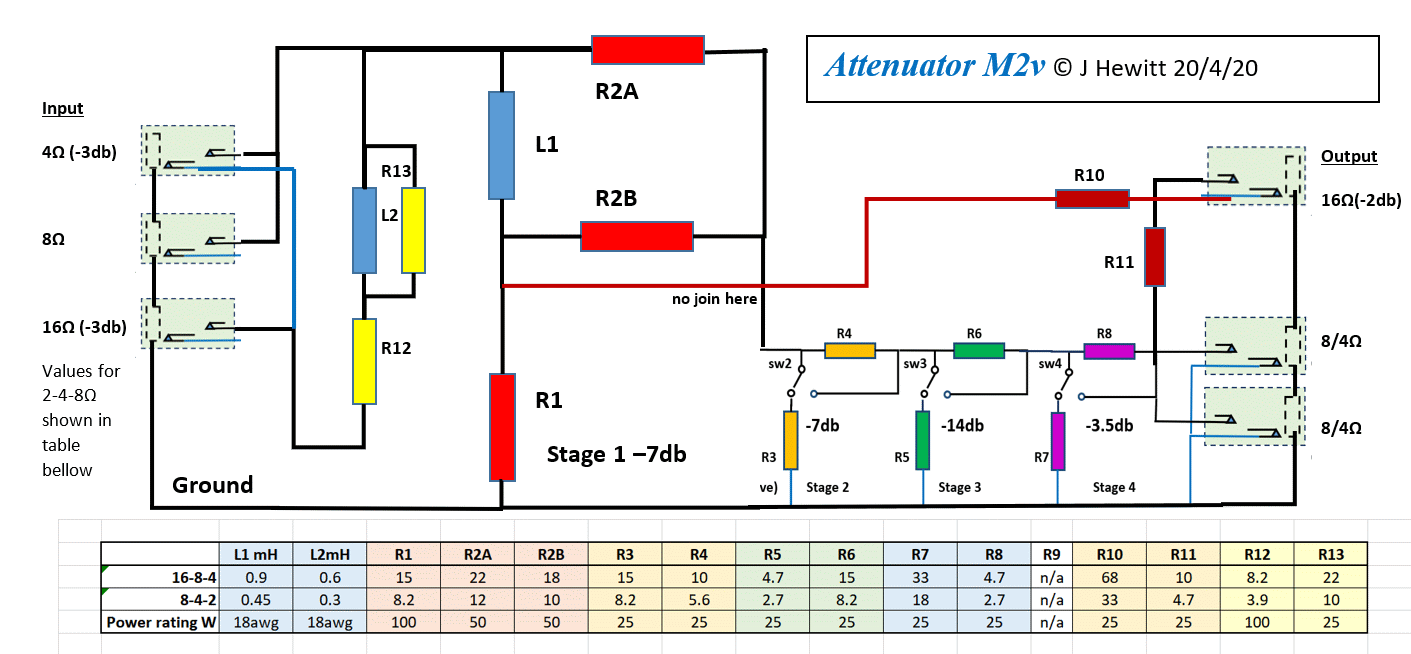
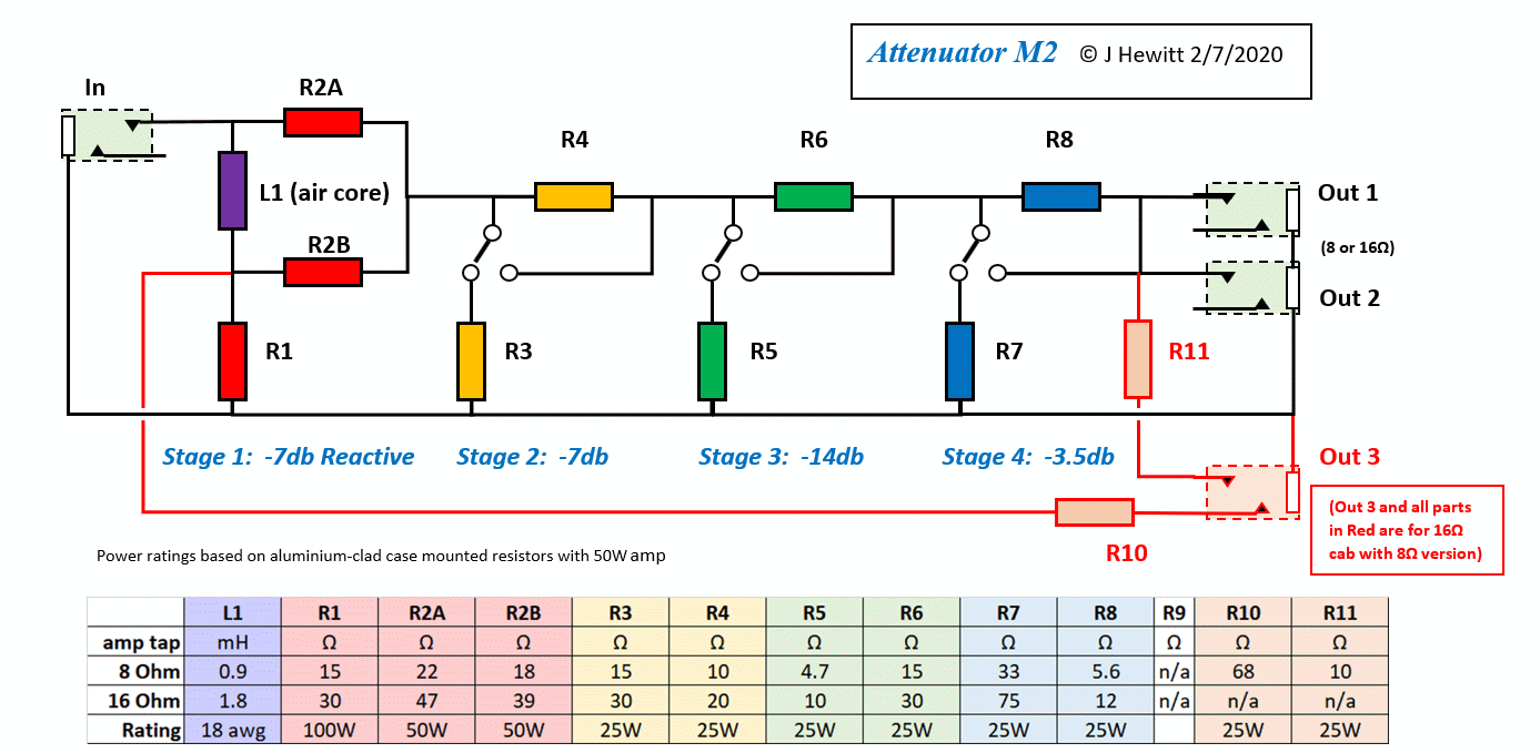
Hi Eoin - thanks for your interest. M2v was the one where I added an extra front-end circuit to help it deal with different amp taps. Its based closely on M2, which is dedicated to one amp ohms. But both can work with different speaker Ohms. Just raising that since most folk could work with just one amp Ohms value, even with a few different amps and different speakers, using either an 8 or a 16 Ohm version of M2.

M2v, in its 16-8-4 version is basically an 8 Ohm M2. The extra circuit adds another reactive stage at the front in either series or parallel, which takes half the power (hence another -3db drop) when you engage it. This will keep the tone consistent when using the different taps, and is better than some other popular commercial models which just slap a resistor or two in front.

Here's the two drawings:


The designs are fine, but M2 got a new better drawing, whereas the M2v drawing was made up out of parts! Thanks for your comments on the drawings. I just do them in MS Word, and making the loop-overs is too fiddly for me. I use the colours to separate wires and on the M2 one, I slipped a small white break between wires that cross. Ive tried dots for connections too, and sometimes they don't align properly. But, I don't do many of these, and the attenuators are quite simple diagrams so people who know enough to be using them don't seem to go wrong with them.

For your 100 watt versions, yes basically double all resistor watt ratings. Id suggest to use a series or parallel pair to double the 100W ones, and separate the two halves to spread the heat out. Also, consider the switch current ratings and the quality of the jacks. 100W at 8 ohms is 3.5Amps and youd want at least double that as a spec. As drawn, they don't have a full bypass, so you don't need to switch the full current, but it all has to go through jack contacts. In M2v, I used extra contacts on a stereo jack to engage the additional front end. Itd be more direct just using the 8 Ohm input.

If you use a 16 Ohm amp tap, there is less current flowing through contacts. A 16 Ohm M2 will also work fine with 8 Ohm cabs.

On the inductors, if you are doing a 16Ohm M2 build, I think its OK at 18 or 16 gage but Id go with 16 (or 15) if you are doing 8 ohm for M2 or M2v. All air core, no steel bolts.

My builds have all been for my 40 and 50W amps, and I just don't find that they get very hot. But at 100W, particularly one cranking at more than that, the physics says that they just have to get toasty! Ventilation from below and above and a big thick aluminium case with lots of holes is key. Could also consider a fan system. But if you have the resistors all bolted with thermal grease onto a good base, any heating takes quite a while to build up. With steady input, mine take at least a half hour continuous to get to a stable temperature.
 

Latest posts


Top