• We are looking to make improvements to the Classifieds! Help us determine what improvements we can make by filling out this classifieds survey. Your feedback is very appreciated and helpful!

    Take survey

Simple Attenuators - Design And Testing

  • Thread starter JohnH
  • Start date
  • This site may earn a commission from merchant affiliate links like Ebay, Amazon, and others.

JohnH

Well-Known Member
Joined
May 31, 2008
Messages
6,157
Reaction score
5,062
Location
Wilton NSW
Hi John,

Thanks for all of your hard work and contributions on this and the various other projects you've come up with for us guitarists (I've built and installed your buffer in one of my guitars).

I built what I think is the M1 version of this attenuator a couple of years ago and it works well.

I've since acquired a Tone King Sky King which has two built in attenuators and I really like having them on board and I like the functionality of the rotary switch.

I'm working on building a single channel deluxe reverb in a princeton reverb chassis, and I would like to include this attenuator on a rotary switch as a sort of master volume.

I've reviewed the new M2 design as well as your previous design which incorporates a rotary switch, and come up with the following:

PXL_20210618_182837798-M.jpg


My goal is to have a six position rotary switch with the following db reductions: 0, 7, 14, 21, 28, 35

Am I on the right track here? Do the values look right?

Thanks again for all of your help and all of your contributions.

Sincerely,

hoost

Hi hoost, thanks for your interest and good to hear the M that you built before worked out well.

Doing these with a rotary as you describe is trickier than you might expect and i dont think that diagram will work rightly. To make these designs work its essential to keep control of both input and output impedances, for the safety of the amp and the consistency of the tone. It looks like the sketch is based around 8 Ohms, but I see that at minimum setting, the amp will see the 3.75 Ohm resistor, and output impedance varies widely.

The other issue is that if the switch is dealing with the full output as there, it needs to be rated for the full current from the amp which is several amps. Its very hard to find rotaries to do that.

Using the toggle switches allows a wide variation of settings, with plenty of switch rating, and each setting optimized for consistent results.
 

Mjh36

Active Member
Joined
Nov 27, 2020
Messages
157
Reaction score
133
Adding mine to the pile. Thanks to all the heavy hitters here, I've learned a lot. 50w 8 0hm M2 w/ additional 16 Ohm out, 10k line out pot, Hammond 1590F enclosure. I went with Mouser for the enclosure and resistors, PartsExpress for the coil as mentioned in earlier posts. The switches are 15 Amps from Tayda, so a little big but that's ok. Various gauges of wire for fun, 14,16,18 awg.

I don't have a tube amp yet but it sure looks nice! It'll be paired with a 20w Jet City style amp eventually. I got what looked like normal readings when using a speaker and measuring the input. It read between about 8 to 10.5 Ohms in all the positions. I might add lights... I messed up on two holes on top so I added umbrellas for cooling. I may have a couple more questions but I'll put that in another post. This is in the top ten for the greatest threads on the entire internet.

20210619_004746.jpg

20210619_005126.jpg
20210619_004901.jpg 20210619_004928.jpg 20210619_004942.jpg
 
Last edited:

musicheals

New Member
Joined
Jun 3, 2021
Messages
11
Reaction score
7
Today I tested with a Vibrolux reverb, Princeton reverb, a JCM 800 and a 20 watt Marshall....
No change in tone and feel at all. The attenuation steps are very practical and need no change. Well done John and thank you so much! My air brake will get retired.
Next I will try a foot switchable attenuation for stage use.

musicheals
 

hoost

New Member
Joined
Jun 15, 2021
Messages
9
Reaction score
2
Hi hoost, thanks for your interest and good to hear the M that you built before worked out well.

Doing these with a rotary as you describe is trickier than you might expect and i dont think that diagram will work rightly. To make these designs work its essential to keep control of both input and output impedances, for the safety of the amp and the consistency of the tone. It looks like the sketch is based around 8 Ohms, but I see that at minimum setting, the amp will see the 3.75 Ohm resistor, and output impedance varies widely.

The other issue is that if the switch is dealing with the full output as there, it needs to be rated for the full current from the amp which is several amps. Its very hard to find rotaries to do that.

Using the toggle switches allows a wide variation of settings, with plenty of switch rating, and each setting optimized for consistent results.

Hi John,

Thanks for your reply!

As I have it now, the 3.75 ohm resistor would be seen in the maximum attenuation setting.

The resistors on the left are the "parallel resistors", with the top most setting being 0 db attenuation.

The resistors on the right are the "series resistors".

So the first stage switches in the reactive load stage as in your M2 design, only on the series side.

The following four stages are based around the -7db stage in the M2.

Position 1 (0 db): no resistors engaged
Position 2 (-7 db): M2 reactive load stage on the series side of the switch
Position 3: (- 14 db) M2 reactive load + 10 ohms in series tip to tip | 15 ohms in parallel to ground
Position 4: (-21 db) M2 reactive load + 10 ohms + 10 ohms series | 7.5 ohms in parallel to ground
Position 5: (-28 db) M2 reactive load + 10 ohms + 10 ohms + 10 ohms series | 5 ohms in parallel to ground
Position 6: (-35 db) M2 reactive load + 10 ohms * 4 series | 3.75 ohms in parallel to ground

Does that make sense?

Thanks!

hoost
 

hoost

New Member
Joined
Jun 15, 2021
Messages
9
Reaction score
2
Hi hoost, thanks for your interest and good to hear the M that you built before worked out well.

Doing these with a rotary as you describe is trickier than you might expect and i dont think that diagram will work rightly. To make these designs work its essential to keep control of both input and output impedances, for the safety of the amp and the consistency of the tone. It looks like the sketch is based around 8 Ohms, but I see that at minimum setting, the amp will see the 3.75 Ohm resistor, and output impedance varies widely.

The other issue is that if the switch is dealing with the full output as there, it needs to be rated for the full current from the amp which is several amps. Its very hard to find rotaries to do that.

Using the toggle switches allows a wide variation of settings, with plenty of switch rating, and each setting optimized for consistent results.

Also, regarding the switch, I'm not sure if I'm doing the calculation perfectly, but I figured 22W at worst case 4 ohms is a maximum current of 2.35A, so if I got a switch that can handle 3A it should be able to handle the load.

Does that sound right?

They're not cheap but they are available and for me the convenience of having everything in one package as well as the aesthetics are worth the price.

Thanks again!
 

JohnH

Well-Known Member
Joined
May 31, 2008
Messages
6,157
Reaction score
5,062
Location
Wilton NSW
Hi @hoost

If you have a 3A switch with the right poles, and its just for a 22W amp then yes that's fine.

But on the wiring, on my diagrams, the -7db reactive stage is always first in line after the amp, before the switched stages. So the amp never sees the low parallel resistors directly and always sits reasonably close to the ohms that it expects.

Also, the basic two-resistor arrangement of each stage works best at -7db, and works well at 1/2x or 2x that if its after Stage 1. Outside of that range the tone starts to drift away from being an tone match.

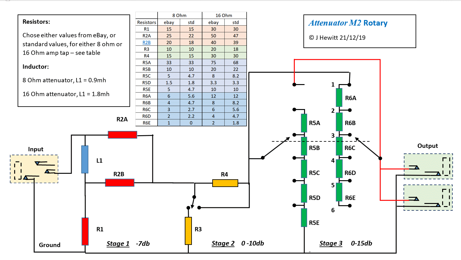
I did have a go at a rotary version, which used rotary for a 0 to -15db range, and another fixed stage:


JohnH

Well-Known Member
Joined
May 31, 2008
Messages
6,157
Reaction score
5,062
Location
Wilton NSW
Today I tested with a Vibrolux reverb, Princeton reverb, a JCM 800 and a 20 watt Marshall....
No change in tone and feel at all. The attenuation steps are very practical and need no change. Well done John and thank you so much! My air brake will get retired.
Next I will try a foot switchable attenuation for stage use.

musicheals

That's great news! In one session you have tested the design with most of the key amp types!
 

hoost

New Member
Joined
Jun 15, 2021
Messages
9
Reaction score
2
Hi @hoost

If you have a 3A switch with the right poles, and its just for a 22W amp then yes that's fine.

But on the wiring, on my diagrams, the -7db reactive stage is always first in line after the amp, before the switched stages. So the amp never sees the low parallel resistors directly and always sits reasonably close to the ohms that it expects.

Also, the basic two-resistor arrangement of each stage works best at -7db, and works well at 1/2x or 2x that if its after Stage 1. Outside of that range the tone starts to drift away from being an tone match.

I did have a go at a rotary version, which used rotary for a 0 to -15db range, and another fixed stage:


Hi John,

This is what I modeled the concept on, but instead of having stage 1 fixed, I moved it between pins 1 and 2 on the series side of the rotary switch and attempted to balance out the remaining stages for an additional -7 db each.

I'm just starting to wrap my head around the math of the additional resistive stages so I may need to tweak them a bit, but the M2 -7 db stage was using 10 ohms in series and 15 ohms in parallel, so that's what I targeted.

Rotary%20Switch%20Attenuator%20v0-M.png


Thanks,

hoost
 

JohnO9

New Member
Joined
May 4, 2021
Messages
6
Reaction score
16
Hi John,
In my search for a DIY attenuator I came to this thread somewhere around page 82. Reading it completely, it looked perfect to build. I've just finished an M2 version and it works well - maintains tone with attenuation with my Tweed Deluxe and varients.
The case is made around a heatsink from Parts Express, where I also got the switches and inductor. Aluminum L pieces form the chassis, with a slot at the bottom for air flow. The inductor is mounted on a plastic piece that came with the heatsink. The resistors are from Digikey, and vinyl graphics from IndCom.
Thanks for this project. JohnO
 

Attachments

  • M2-1p.pdf
    107 KB · Views: 69
  • M2-3p.pdf
    73.1 KB · Views: 41
  • M2-4p.pdf
    72.3 KB · Views: 36
  • M2-2p.pdf
    92.4 KB · Views: 49

Gene Ballzz

Well-Known Member
Joined
Feb 19, 2013
Messages
4,697
Reaction score
6,521
Location
Las Vegas, NV
Hi John,
In my search for a DIY attenuator I came to this thread somewhere around page 82. Reading it completely, it looked perfect to build. I've just finished an M2 version and it works well - maintains tone with attenuation with my Tweed Deluxe and varients.
The case is made around a heatsink from Parts Express, where I also got the switches and inductor. Aluminum L pieces form the chassis, with a slot at the bottom for air flow. The inductor is mounted on a plastic piece that came with the heatsink. The resistors are from Digikey, and vinyl graphics from IndCom.
Thanks for this project. JohnO

Looks great and :welcome: to this fantastic forum! Yes, these attenuators are the holy grail of the whole genre!
Just Sayin'
Gene
 

JohnH

Well-Known Member
Joined
May 31, 2008
Messages
6,157
Reaction score
5,062
Location
Wilton NSW
hi @JohnO9 , thanks for posting. It looks badass with that heatsink and i like the rocker switches, much sleeker than the usual toggles.
 

hoost

New Member
Joined
Jun 15, 2021
Messages
9
Reaction score
2
Okay, I've taken another stab at the rotary switch concept.

My goal being to get the following attenuation levels on a rotary switch to be built into an amp (similar to my Tone King Sky King with Ironman Attenuator):

0 db
-7 db
-14 db
-21 db
-28 db
-35 db

In this layout I'm proposing using a 6 position, 4 pole rotary switch.

This would allow me (hopefully) to utilize JohnH's already proven -7db and -14db attenuation stages.

See any issues with the layout?

35db%20Attenuator%20Rotary%20Switch-L.jpg


The biggest issue aside from the layout will be the cost and availability of a rotary switch with an adequate number of poles and a sufficient current rating for the amp's load.

In doing some digging, there are many folks at the amp garage who were building the air brake attenuator using a Lorin rotary switch (CK1455) with no issues for use with amps at least as large as 50W; this switch is rated for only 150mA.

I am eyeing a 6 position, 2 pole, 2 deck rotary switch made by Grayhill, which is rated for 1A. They have a shorting version (44D30-02-2-AJS) and a non-shorting version (44A30-02-2-06N). Both retail for around $60. Any thoughts on which is preferable? I would think the shorting version, but I haven't fully considered the risks.

Thanks!
 

JohnH

Well-Known Member
Joined
May 31, 2008
Messages
6,157
Reaction score
5,062
Location
Wilton NSW
hi @hoost

You are the best to judge what risks you want to take with switch ratings for your gear, and I don't know enough to advise on if ratings can be exceeded. It could be said that switch ratings are based on actually switching those amps and volts under load, whereas the sensible attenuator user will only move the switches when not under load (at least, not playing at that moment). But then, what if you strummed a mighty power chord and then dialed in your volume while it rang out? If contact failure leads to an open circuit under high output, out pops the output tubes with possible OT damage (and ive done that!)

Your switch diagram looks ok to me and seems to get the connections as intended. I think make before break is the way to go.

The switch that you linked looks to be 2-pole though. What you are finding is why I haven't gone very far with rotary versions of these units, since they are way simpler with the separate two-position switches. You quickly get used to it and you get more different settings available too.
 

hoost

New Member
Joined
Jun 15, 2021
Messages
9
Reaction score
2
hi @hoost

You are the best to judge what risks you want to take with switch ratings for your gear, and I don't know enough to advise on if ratings can be exceeded. It could be said that switch ratings are based on actually switching those amps and volts under load, whereas the sensible attenuator user will only move the switches when not under load (at least, not playing at that moment). But then, what if you strummed a mighty power chord and then dialed in your volume while it rang out? If contact failure leads to an open circuit under high output, out pops the output tubes with possible OT damage (and ive done that!)

Your switch diagram looks ok to me and seems to get the connections as intended. I think make before break is the way to go.

The switch that you linked looks to be 2-pole though. What you are finding is why I haven't gone very far with rotary versions of these units, since they are way simpler with the separate two-position switches. You quickly get used to it and you get more different settings available too.

Thanks John.

The 44D30-02-2-AJS switch linked above is two poles per deck, with two decks, so I think it should work.

For those looking in the future, here is another option with a 5A current rating:

44A45-04-1-06S

Mouser doesn't stock that part so I'm not sure on lead time or minimum order quantity.

I do have the multi-switched version M as a standalone unit and it does work well.

After having the Tone King, I'm hung up on the rotary switch concept built into the amp (I'm getting ready to build a single channel deluxe reverb with no tremolo in a Princeton chassis), so I think I'm going to push forward with the idea.

Thanks again for all of the help, and all of your great contributions to the community. As I mentioned before, I recently built and installer your buffer in my PRS McCarty and I love it, too. Thank you.
 

Gene Ballzz

Well-Known Member
Joined
Feb 19, 2013
Messages
4,697
Reaction score
6,521
Location
Las Vegas, NV
@hoost
An observation and/or suggestion, without analyzing your switch wiring (I'm horrible with switch configurations/interactions) or doing the math. If you take the 0db option off of the rotary and control that via a "bypass" toggle switch of high enough current rating (4 to 5 Amps) the current requirement for all the subsequent stages on the rotary drops dramatically. Make it so that the first, initial reactive stage is always activated, anytime the unit is not in "bypass" mode. That also takes away the need for two switch positions. Likely an easier to find switch. Then add a -3.5db stage that can be added on to any/all of the other stages, via a fairly low current rated toggle, to get those in between settings. Trust me when I tell you that -3.5db up/down fine tuning helps get to the best sweet spots!
Just My Considered Experience!
Gene
 

hoost

New Member
Joined
Jun 15, 2021
Messages
9
Reaction score
2
@hoost
An observation and/or suggestion, without analyzing your switch wiring (I'm horrible with switch configurations/interactions) or doing the math. If you take the 0db option off of the rotary and control that via a "bypass" toggle switch of high enough current rating (4 to 5 Amps) the current requirement for all the subsequent stages on the rotary drops dramatically. Make it so that the first, initial reactive stage is always activated, anytime the unit is not in "bypass" mode. That also takes away the need for two switch positions. Likely an easier to find switch. Then add a -3.5db stage that can be added on to any/all of the other stages, via a fairly low current rated toggle, to get those in between settings. Trust me when I tell you that -3.5db up/down fine tuning helps get to the best sweet spots!
Just My Considered Experience!
Gene

Thanks Gene. I will stew on the idea for a bit.

What I've found with my Sky King is I'm usually either on the -15db or the -24db setting. Rarely will I go to the -36db. If I'm going to play that quietly I just pop on my Waza air headphones. That being a 40W amp, and this amp I'm planning to build being a 22W, it might indeed make sense to have the 3.5db increment, but I might go something like 0, 7, 10.5, 14, 17.5, 21.

I think at this point I might just have to build it and see what works for me. I can always swap resistor "attenuation stages" around until I get it dialed in.

Doing the bypass switching as you describe would certainly work, but I'm not too hung up on the cost of the switch and the cleanliness and simplicity of the interface is worth the cost to me. If I burn up the switch and some tubes and transformers I might change my mind pretty quickly though!

Thanks!
 

JohnH

Well-Known Member
Joined
May 31, 2008
Messages
6,157
Reaction score
5,062
Location
Wilton NSW
All ok, but i have just a couple more thoughts:

The idea of having at least the bypass function as a separate switch seems like a very sensible and practical feature. The 'bypassed' or 'not-bypassed' change is where the greatest care is needed to ensure everything is connected up, under control and your signal zero, to avoid nasty transients. Shorting contacts (make-before-break) should be fine but a bit of dirt or aging contacts and you could start to get the nastinesses on every switch move. But if you get reactive stage 1 fully engaged before the rotary its all a lot safer, and you are less likely to go to that bypass mode inadvertently.

And then you get two more benefits:
  • The max current through the rotary switch is about halved and actually, at 22w and 8 Ohms, its halving from 1.7A to 0.85A so that switch is then working within spec.
  • Plus, you have an extra switch position for an attenuated setting. To make the most of that feature, we can change the attenuation values of each stage to make them closer, see as follows:

On the basic designs, the three resistive stages each have two resistors. In theory, the ideal db value for these, based on this design is the -7db stage, which is why this setting is used in stage 1 and also 2. But, for stage 2 , 3 and 4, they also work fine either side of that in the range from about -3db to -15db provided reactive Stage 1 is first. M and M2 therefore use -3.5, -7 and -14db.

But, its pretty easy to work out sets of values for resistive stages anywhere within the range. This, together with the spare knob position and a choice that you don't really need to go to such a low setting, could allow you to set closer spacings between attenuation levels.

eg, you could use 4db steps and have:
-0db Fully bypassed
-7db Reactive Stage 1, then:
-11, -15, -19, -23, -27 db

or 5 db steps:
-0db Fully bypassed
-7db Reactive Stage 1, then:
-12, -17, -23, -28, -33 db

If any of that is of interest, Id be happy to run numbers for it.
 

hoost

New Member
Joined
Jun 15, 2021
Messages
9
Reaction score
2
All ok, but i have just a couple more thoughts:

The idea of having at least the bypass function as a separate switch seems like a very sensible and practical feature. The 'bypassed' or 'not-bypassed' change is where the greatest care is needed to ensure everything is connected up, under control and your signal zero, to avoid nasty transients. Shorting contacts (make-before-break) should be fine but a bit of dirt or aging contacts and you could start to get the nastinesses on every switch move. But if you get reactive stage 1 fully engaged before the rotary its all a lot safer, and you are less likely to go to that bypass mode inadvertently.

And then you get two more benefits:
  • The max current through the rotary switch is about halved and actually, at 22w and 8 Ohms, its halving from 1.7A to 0.85A so that switch is then working within spec.
  • Plus, you have an extra switch position for an attenuated setting. To make the most of that feature, we can change the attenuation values of each stage to make them closer, see as follows:

On the basic designs, the three resistive stages each have two resistors. In theory, the ideal db value for these, based on this design is the -7db stage, which is why this setting is used in stage 1 and also 2. But, for stage 2 , 3 and 4, they also work fine either side of that in the range from about -3db to -15db provided reactive Stage 1 is first. M and M2 therefore use -3.5, -7 and -14db.

But, its pretty easy to work out sets of values for resistive stages anywhere within the range. This, together with the spare knob position and a choice that you don't really need to go to such a low setting, could allow you to set closer spacings between attenuation levels.

eg, you could use 4db steps and have:
-0db Fully bypassed
-7db Reactive Stage 1, then:
-11, -15, -19, -23, -27 db

or 5 db steps:
-0db Fully bypassed
-7db Reactive Stage 1, then:
-12, -17, -23, -28, -33 db

If any of that is of interest, Id be happy to run numbers for it.

Hi John,

I'm still kicking around the idea of a bypass switch and I do think it has a lot of practical benefits. Maybe I'd put the toggle above the rotary switch kind of how Dumble does some switches above the pots.

If it's not too much trouble to run the numbers for the 4 and 5 db steps, I'd certainly appreciate it, and I would imagine there may be some others who come along later who might find it useful.

I think I'd be inclined to start with the 4 db steps, although it's hard to know until you crank it up!

Thanks again!
 

JohnH

Well-Known Member
Joined
May 31, 2008
Messages
6,157
Reaction score
5,062
Location
Wilton NSW
No problem, here they are:

4and8db210630.gif

To get the 4db steps, you'd need one -4db stage and two at -8db. Or for 5db steps, a 5 and two 10's.

The values are shown above. If you cant get a 6 Ohm, get 5.6.

The plots are based on the 4 db steps, including with stage 1 being the -7db reactive stage, followed by the resistor stages. Its running the whole circuit analysis including a speaker sim model.

Red represents the full unattenuated speaker response, then you can see the calculated attenuated plots below it, in fairly even steps each close to 4db. At right, all the plots are normalised to the same volume so you can see the consistency of the predicted tones. The 5 and 10 db values produce an equivalent pair of plots.
 

hoost

New Member
Joined
Jun 15, 2021
Messages
9
Reaction score
2
No problem, here they are:

View attachment 90920

To get the 4db steps, you'd need one -4db stage and two at -8db. Or for 5db steps, a 5 and two 10's.

The values are shown above. If you cant get a 6 Ohm, get 5.6.

The plots are based on the 4 db steps, including with stage 1 being the -7db reactive stage, followed by the resistor stages. Its running the whole circuit analysis including a speaker sim model.

Red represents the full unattenuated speaker response, then you can see the calculated attenuated plots below it, in fairly even steps each close to 4db. At right, all the plots are normalised to the same volume so you can see the consistency of the predicted tones. The 5 and 10 db values produce an equivalent pair of plots.

Excellent!

Thanks so much for all of your help John. I really appreciate it.

It will probably take a few months to get the amp design reviewed and built, but I will report back when everything is up and running with how it works.

Thanks!
 

Latest posts


Top