mike_lawyer
Member
- Joined
- Sep 2, 2019
- Messages
- 32
- Reaction score
- 5
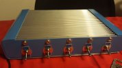
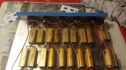
I have all of the components set in my box, about to begin the wiring. Maybe a silly question, but the air core inductor has a lead that is on the outside of the ring of wire, and a lead that goes to the middle of the ring of wire. Does it make any difference which lead is wired to the input jack and which one goes to the resistors?
")