• We are looking to make improvements to the Classifieds! Help us determine what improvements we can make by filling out this classifieds survey. Your feedback is very appreciated and helpful!

    Take survey

Simple Attenuators - Design And Testing

  • Thread starter JohnH
  • Start date
  • This site may earn a commission from merchant affiliate links like Ebay, Amazon, and others.

AtomicRob

Well-Known Member
Joined
Feb 4, 2009
Messages
655
Reaction score
776
Location
California
Hi all and @JohnH ,

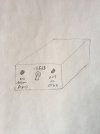
After a long hiatus, I finally have time again to pick up my M2 build project. I've got all the parts and I'm trying to figure out a clean layout for my chassis. This is what I have now:

View attachment 130736

👀 That's looks like it will be a really nice chassis, is that going to be custom built or did you buy it like that? (And if so where did you find it?)

I'd also suggest moving the 25W resistors to the side on the other heat sink - the wiring won't be as neat but heat management is more important. I built a 100W version in a similar heat sink chassis and positioned everything based on heat dissipation rather than wiring efficiency - doesn't look as pretty inside but that's ok.

One trick I did while assembling it was to print out the original schematic, and then use colored pens to trace the wires as I added them, using the matching color of the wire. It's especially helpful when the physical arrangement doesn't match the schematic layout (which is usually the case anyway) - all that really matters is connecting the right nodes.
 

Dretot

New Member
Joined
Feb 9, 2022
Messages
19
Reaction score
13
Hello JohnH and fellow lovers of cranked amp tone. I've been reading this thread for some time now and I would like to build one of your attenuators. I have good workshop/soldering skills, but I fail the "entrance exam". I can't put together a circuit on a schematic alone, I need a picture layout. I've seen several in this thread, but not for the specific version I'm looking for.

I would like to build a 100w 8ohm Basic version, but only the 1st stage with a -3.5/ -7dB switch and 1 speaker out.

I play through a 100w Marshall slp, 2 tubes pulled with a variac at 100v. Amp is set at 8ohm to a 16ohm 4x12. I have a master volume and I can get close to where the amp starts to sing, but its just a bit too loud. If I could knock off a few dB's I'd be very happy.

If anyone can help me out, I would appreciate it.

thank you,
andreas
 

JohnH

Well-Known Member
Joined
May 31, 2008
Messages
6,155
Reaction score
5,062
Location
Wilton NSW
Hi @Dretot , thanks for your interest, Such a diagram isn't too hard, Id be happy to help.

But a few questions and comments from what you noted above:

Pulling two tubes to cut power out is a classic work-around. And when you do, the labelled 8 Ohm out that you use is now a 16 Ohm out. And you put that to your 16 Ohm cab, so all good. Also, I understand that due to the reduced draw on the power supply, the B+ voltage can rise somewhat, adding stress to the circuit and the remaining tubes. But you have a variac set to reduce voltage, so again all good!

Do you want to keep with this 2-tube/variac setup for using the attenuator? If so, it seems like you may need a 16 Ohm version, and maybe its just for 50W? (no prob building for 100W though). Or do you want to put the tubes back in and run at 100W? then maybe also at 16 Ohm to suit the cab?

Although there will be few parts, still build it in a good-sized box to spread heat, and also its a nice easy and spacious wire-up. Probably add a fan - easiest just from a wall-wart supply and use it if it gets too hot
 

Gene Ballzz

Well-Known Member
Joined
Feb 19, 2013
Messages
4,697
Reaction score
6,521
Location
Las Vegas, NV
Hello JohnH and fellow lovers of cranked amp tone. I've been reading this thread for some time now and I would like to build one of your attenuators. I have good workshop/soldering skills, but I fail the "entrance exam". I can't put together a circuit on a schematic alone, I need a picture layout. I've seen several in this thread, but not for the specific version I'm looking for.

I would like to build a 100w 8ohm Basic version, but only the 1st stage with a -3.5/ -7dB switch and 1 speaker out.

I play through a 100w Marshall slp, 2 tubes pulled with a variac at 100v. Amp is set at 8ohm to a 16ohm 4x12. I have a master volume and I can get close to where the amp starts to sing, but its just a bit too loud. If I could knock off a few dB's I'd be very happy.

If anyone can help me out, I would appreciate it.

thank you,
andreas

@Dretot
@JohnH said exactly what I was thinking!
Simply Attenuatin'
Gene
 

Dretot

New Member
Joined
Feb 9, 2022
Messages
19
Reaction score
13
Thank you John, This is great! and yes, you are right, I probably need a 16 Ohm version.

I will always run the amp with the 2-tube/variac configuration. I love the squishy feel and lowered power.

I think it should be 100W, just to be safe. I'm not sure exactly how much power my amp is putting out so I would feel better with the higher power rating.

What dimensions should I be looking for the enclosure? I see one member used the Hammond 1550G. It's roughly 9"x 6"x 2". Is 2" deep enough? or should I look for slightly deeper?

thanks again,
andreas
 

JohnH

Well-Known Member
Joined
May 31, 2008
Messages
6,155
Reaction score
5,062
Location
Wilton NSW
Sounds like a good plan.

Im thinking in a Hammond case, have the lid at the base, drilled for heaps of ventilation, and mount the fan to it, pointing to blow upwards onto the R1 resistors. Then mount all the components, switch and jacks to the main part of the case, now the top, together with more vent holes

Having made provision, you could leave the fan to add later if needed, since its independent of the rest

@Gene Ballzz will know if a 100W resistor can fit above a typical 12V brushless fan, within a 2" case? or would 2.5" work better?

@Dretot, once you pick a case, maybe sketch out where the jacks and switch would go to best suit it sitting on your rig.
 

Dretot

New Member
Joined
Feb 9, 2022
Messages
19
Reaction score
13
Ok, I like your idea for mounting the fan and resistors. I found a BUD box, 6.5"x 5"x 3" should be deep enough, but is it big enough overall?

Here's a sketch of jacks and switch.
 

Attachments

  • bud box.jpg
    bud box.jpg
    861.5 KB · Views: 17

JohnH

Well-Known Member
Joined
May 31, 2008
Messages
6,155
Reaction score
5,062
Location
Wilton NSW
Ok, I like your idea for mounting the fan and resistors. I found a BUD box, 6.5"x 5"x 3" should be deep enough, but is it big enough overall?

Here's a sketch of jacks and switch.
Thanks, do you have an online link for that box?
 

Dretot

New Member
Joined
Feb 9, 2022
Messages
19
Reaction score
13
Forum isn't letting me post a link. It's on Amazon, search...

BUD Industries CN-5708 Die Cast Aluminum Enclosure 6.51" L x 5.01" W x 3.05" H, Natural​


mgee1960

New Member
Joined
Nov 29, 2022
Messages
19
Reaction score
7
Location
Maryland
I use a volume pot thru the send & return loop, it works great & so easy to make. Just a jack cord cut & connected to a volume pot
 

JohnH

Well-Known Member
Joined
May 31, 2008
Messages
6,155
Reaction score
5,062
Location
Wilton NSW
I use a volume pot thru the send & return loop, it works great & so easy to make. Just a jack cord cut & connected to a volume pot

Thanks for posting. That's a simple way to add a Master Volume, particularly for an amp that doesn't have one. What it can't do though is to allow the power tubes to be driven so that they compress and distort and add their own harmonics and tone, (assuming that is what is wanted). That's why the designs in this thread go after the amp output.
 

DMarsh

New Member
Joined
Feb 25, 2019
Messages
2
Reaction score
0
Hi Gene. I've successfully built two 2-ohm attenuators and have been gigging with them for over 3 years with great success. They are used with vintage Super Reverbs. The first one has switches to choose between 4 different attenuation levels. I soon realized that the -7.5 db level was all I ever needed for live shows, so I built a single stage one with a single inductor coil (M2 design I believe?). Used 16 ga stranded wire throughout. I set the super reverb to about 9 on the volume for 3-4 hour shows and the attenuator just barely gets warm. The tone is incredible and totally blew away my commercially-bought 2 ohm attenuator. I'd be happy to provide more specifics of the build. Just let me know 😁
Hey @JohnH , didn't a dedicated 2 ohm unit get designed and built for use with a Super Reverb, along with it's 2 ohm speaker load? I searched, but couldn't find it!
Thanks Again Sir,
Gene
 

DMarsh

New Member
Joined
Feb 25, 2019
Messages
2
Reaction score
0
Hi Gene. I've successfully built two 2-ohm attenuators and ha ve been gigging with them for over 3 years with great success. They are used with viThe first one has switches to choose 4 different attenuation levels. I soon realized that
Hey @JohnH , didn't a dedicated 2 ohm unit get designed and built for use with a Super Reverb, along with it's 2 ohm speaker load? I searched, but couldn't find it!
Thanks Again Sir,
Gene

HI Gene

I guess its everything to do with current that would need to be considered. Im not sure what amp power can come from these 2 Ohm Fenders? If its like 135W from the big Twins, then into 2 Ohms, and without further overdrive allowance, that's a current of:
sqrt (135 / 2) = 8.2 Amps

Wire for hook-up and coil could be upgraded to suit, as could the switches. But what about jacks? I think Cliff jacks are rated for 5 Amps. Id assume the amps use jack sockets as usual. I wonder if this issue is addressed, or is it found not to be a problem? or is the amp power a lot less?
Hi John. I realize that I'm a bit late to the party on this, but I used Switchcraft Z15J 1/4" jacks for the 2 ohm builds. They are rated for 15A. I was able to overcome the chassis grounding issue by drilling the holes a bit wider and using thin plastic washers on each side. I used these instead of the supplied metal ones. They have worked great so far.

-Derek
 

JohnH

Well-Known Member
Joined
May 31, 2008
Messages
6,155
Reaction score
5,062
Location
Wilton NSW
hi @DMarsh , thanks for posting about your 2 Ohm builds. It's great to hear that they're working well. Good idea with the high current jack. If you'd like to, we have a thread for the builds here, which you could post some pics to:


We now have values for 2 and 4 Ohm builds in post #1, for those playing these classic old Fenders.
 

JohnH

Well-Known Member
Joined
May 31, 2008
Messages
6,155
Reaction score
5,062
Location
Wilton NSW
Hi again @Dretot

Ive been laying out a few resistors on a diagram to try to visualize the sizes of parts, for your 100W basic M4 stage 1. I think we need a bigger box!

This picture is pretty close to scale, based on the dimesnions of the box that you found, and the spec sizes of Arcol resistors. Basicaly, to do it right at 100W, we need 5 x 100W resistors per the diagram. Its actually more compact to use 2x 50W for each, due to smaller tabs. So that's 10 resistors laid out across the bottom of the box (which would be the top in use), with switches and jacks on the side and fan and coil on the lid = base.

But its just a bit tight for those 10 and the sides are not real good due to the ribs. Here's a pic to scale, with the box, some 50W Arcol and a 100W Arcol:

m4parts.gif

Shall we find something more spacious? I think it will be much better then!
 

Dretot

New Member
Joined
Feb 9, 2022
Messages
19
Reaction score
13
John, Thank you so much for helping me out with this. The BUD box does look to be to small, good thing I'm waiting on your ok :)

Here's a 1590F Hammond that is 7.4" x 7.4" x 2.6".

I'll look for one slightly bigger in case the 1590F isn't big enough.
 

Dretot

New Member
Joined
Feb 9, 2022
Messages
19
Reaction score
13
Still can't post a link. It's on Amazon.

Hammond 1590F Aluminum Diecast Case​


Latest posts


Top