Replaced Jcm Dsl 100 Board... Still Having Problems!

ampmadscientist

Well-Known Member
Joined
Jun 26, 2014
Messages
17,849
Reaction score
12,230
Location
Bio-Isolation Lock Down
Jeese, pin #2 is -52V.

Man, bring this thing to a qualified technican.

Ampmad the scientist, you should stop now.

I am a qualified technician.
And I am one hell of a lot more qualified than you are.
Remember this:
Iv'e repaired more guitar amps than you have seen in your entire life. I don't need any help from you.
 

ampmadscientist

Well-Known Member
Joined
Jun 26, 2014
Messages
17,849
Reaction score
12,230
Location
Bio-Isolation Lock Down
Sounds pretty grim, damn! So far, I've done all the tests with the black lead (alligator clip lead) on the chassis. I'll continue that for the powered test (test B). Do I continue this for test A as well, or do I have one lead on each end of the resistors? Cause I've been having some trouble getting accurate readings for test A. The link you shared seems to be the same type of "low quality" pots you mentioned. Not sure how long those last if it's a big concern.
Thanks again for the quick replies and detailed instructions.
It's not grim.
It's just bad bias adjust pots so far...
That's all we found up to now.
Bias pots go bad all the time, and it's easy to change them.

That is a cake-walk.

Keep measuring, and don't give up.
Measurements with your meter are the key to success.

The reason amp techs are so successful in repairing amps: They Measure.
Learn how to do this like a pro.
Spend 5 minutes and measure.
 
Last edited:
  • Like
Reactions: RS_

mickeydg5

Well-Known Member
Joined
Sep 30, 2011
Messages
28,591
Reaction score
16,367
Location
The middle east of the united states of America
D9 and D10 is the source of the bias voltage which should end up at pin 5 of the power tube socket.

It goes
D9 D10 > R 77 > board connector pin 1, board to board cable > bias pots > R67 R69 bias split resistors > pin(s) 5

I know, I can read. I just measured it since I got nothing at pin 5 and wanted to get some readings at all. I mentioned it in case it had any significance.
I am a qualified technician.
And I am one hell of a lot more qualified than you are.
Remember this:
Iv'e repaired more guitar amps than you have seen in your entire life. I don't need any help from you.
Sorry guys. I was not logged in when scanning through post so I did not pay attention to everything including the marked up schematics. I was thinking power tube sockets when you were referencing CON1 pins.

Carry on and guide him through it.
 
Last edited:

0caria

Member
Joined
Oct 1, 2018
Messages
44
Reaction score
0
"I doubt that this bias pot is the only issue or contributing factor to the runaway bias."

You don't have bias. This is a severely contributing factor.

You stated that there was no DC voltage reading at pin 5 of the output tube sockets. You MUST have DC negative voltage at pin 5. There is no choice.

(in fact it may be the only real issue, maybe not)
The pots are fried out from the old circuit board.
The old circuit board was bleeding B+ into the bias circuit. This burned up the bias adjust pots.
Besides which these are very cheap flimsy pots which probably fail anyway...you probably can't find a pot that cheap anywhere, it's the lowest quality pot possible.
jcm-bias-pcb.jpg


Besides replacing the pots, which you must do, there is 2 more tests you can do.

Test A- This is not a powered test. UN-plug the amp from power.

1. Take the output tubes out.
2. With the ohm meter, measure R67 and R69. These resistors should measure 220K ohms each. 220,000 ohms.
Measure R6 and R9, should be 1 ohm each.
R7, R66, R70, R10 should all read the same. I'm not sure what the value is on your new board. Maybe 5.6K?
R 60, R65, R74, R76, should all read 1000 ohms. 1K ohm.

Test B - This is a powered test please be careful.

Take the output tubes out.
1. Connect DC voltmeter to pin 5 of output tube socket. (use a clip lead if you can) Set meter for highest DC voltage this is usually 600 or 1000 volts DC.
2. Turn amp on, leave standby in warm-up position.
3. Turn standby to operate position, Read DC volts at pin 5.
4. Is there any high voltage showing up at pin 5, when you turn the standby to operate position?
Okay, so I did the nonpowered test.
Readings are, R67: 222K R69: 221K
R6 and R9: 1.4 ohms
R7: 5.56K , R66: 5.57K , R70: 5.57K , R10: 5.56K
R60: 0.98K , R65: 0.97K , R74: 0.98K , R76: 0.97K

Will do powered test soon
 

ampmadscientist

Well-Known Member
Joined
Jun 26, 2014
Messages
17,849
Reaction score
12,230
Location
Bio-Isolation Lock Down
Okay, so I did the nonpowered test.
Readings are, R67: 222K R69: 221K
R6 and R9: 1.4 ohms
R7: 5.56K , R66: 5.57K , R70: 5.57K , R10: 5.56K
R60: 0.98K , R65: 0.97K , R74: 0.98K , R76: 0.97K

Will do powered test soon

OK all resistors in that power amp circuit read good.
Now check the pin 5 and see if any high voltage is appearing on that pin...
(do this with power tubes out).

Connect red probe to pin 5 (use clip lead...)
Connect black probe to chassis ground.
Set DC volt meter to highest range: DC 600 or 1000 volts.
Turn power on.
Measure / read DC volts on pin 5, turn standby to operate position.
! (caution high voltage is NOW turned on) !
Make sure that there is no high voltage on pin 5, when standby is in operate position.
Do this / measure this for all the output tube sockets.
Turn power off.

Then when that's done, work on getting the bias voltage back to pin 5 on each output socket.

Pin 5 on each socket should have negative voltage, before turning the standby switch to operate position.
Make sure the negative voltage is on pin 5 before installing tubes.
(you must change the bias adjust pots ---then confirm the bias volts is on pin 5)

If DC negative bias voltage is not on pin 5, the tubes will burn up.
This is very important.

But...
it looks like the only problem may be the bias adjust pots.
 
Last edited:

0caria

Member
Joined
Oct 1, 2018
Messages
44
Reaction score
0
OK all resistors in that power amp circuit read good.
Now check the pin 5 and see if any high voltage is appearing on that pin...
(do this with power tubes out).

Connect red probe to pin 5 (use clip lead...)
Connect black probe to chassis ground.
Set DC volt meter to highest range: DC 600 or 1000 volts.
Turn power on.
Measure / read DC volts on pin 5, turn standby to operate position.
! (caution high voltage is NOW turned on) !
Make sure that there is no high voltage on pin 5, when standby is in operate position.
Do this / measure this for all the output tube sockets.
Turn power off.

Then when that's done, work on getting the bias voltage back to pin 5 on each output socket.

Pin 5 on each socket should have negative voltage, before turning the standby switch to operate position.
Make sure the negative voltage is on pin 5 before installing tubes.
(you must change the bias adjust pots ---then confirm the bias volts is on pin 5)

If DC negative bias voltage is not on pin 5, the tubes will burn up.
This is very important.

But...
it looks like the only problem may be the bias adjust pots.
Okay, so when standby is at warmup, at pin 5 I got -41 V on V5 and V6, and -42V at V7 and V8.
Powered I got -41V across Pin 5 on ALL sockets. Pay attention to V7 and V8, cause there was a slight drop in negative voltage from -42v to -41v. Please let me know what to do next.
 

ampmadscientist

Well-Known Member
Joined
Jun 26, 2014
Messages
17,849
Reaction score
12,230
Location
Bio-Isolation Lock Down
Okay, so when standby is at warmup, at pin 5 I got -41 V on V5 and V6, and -42V at V7 and V8.
Powered I got -41V across Pin 5 on ALL sockets. Pay attention to V7 and V8, cause there was a slight drop in negative voltage from -42v to -41v. Please let me know what to do next.

Everything tests good w/ the tubes out.
I'm worried that the bias adjust pots are bad.
When you measured the bias adjust board:

"In warmup Pin 2 -52V. Pin 6 kept fluctuating and I couldn't get a consistent reading, it also kept sparking at Pin 6 as well. This is all in warmup."

If pin 6 (bias adjust board connector) is fluctuating on the bias adjust board the pot is bad.
This is going to cause the tubes to overheat, and there is going to be drifting of the bias.
This will wreck the output tubes!

You are going to need to change the bias adjust pots. Everything else checked good.
Do not operate the amp until you change the bias adjust pots.

Did you get new output tubes? The old tubes may be bad...
 
Last edited:

0caria

Member
Joined
Oct 1, 2018
Messages
44
Reaction score
0
Everything tests good w/ the tubes out.
I'm worried that the bias adjust pots are bad.
When you measured the bias adjust board:

"In warmup Pin 2 -52V. Pin 6 kept fluctuating and I couldn't get a consistent reading, it also kept sparking at Pin 6 as well. This is all in warmup."

If pin 6 (bias adjust board connector) is fluctuating on the bias adjust board the pot is bad.
This is going to cause the tubes to overheat, and there is going to be drifting of the bias.
This will wreck the output tubes!

You are going to need to change the bias adjust pots. Everything else checked good.
Do not operate the amp until you change the bias adjust pots.

Did you get new output tubes? The old tubes may be bad...
Okay, so that's more relieving to hear.

The tubes are fairly new. I had some problems with drifting bias and some overheating(once or twice) when I first bought the amp back in April this year. I changed the tubes back in June with JJ's to see where the problem lied. The bias remained fairly stable after getting the JJ's, though it did fluctuate a little bit over the course of an hour or two (I would check the bias every time I played it, once after 10 minutes of playing, again after about 45-50 mins of playing).

I played the amp with these new tubes probably less than a dozen times before I then changed the circuit board (cause the bias started drifting more). This takes us to now, where I would continue to blow fuses when I would turn the amp on.
 

0caria

Member
Joined
Oct 1, 2018
Messages
44
Reaction score
0
Okay, so that's more relieving to hear.

The tubes are fairly new. I had some problems with drifting bias and some overheating(once or twice) when I first bought the amp back in April this year. I changed the tubes back in June with JJ's to see where the problem lied. The bias remained fairly stable after getting the JJ's, though it did fluctuate a little bit over the course of an hour or two (I would check the bias every time I played it, once after 10 minutes of playing, again after about 45-50 mins of playing).

I played the amp with these new tubes probably less than a dozen times before I then changed the circuit board (cause the bias started drifting more). This takes us to now, where I would continue to blow fuses when I would turn the amp on.
Just to note, I have not played the amp with the output tubes in it since late September, which was when I started blowing fuses.
 

ampmadscientist

Well-Known Member
Joined
Jun 26, 2014
Messages
17,849
Reaction score
12,230
Location
Bio-Isolation Lock Down
Just to note, I have not played the amp with the output tubes in it since late September, which was when I started blowing fuses.

The unstable operation is due to bias voltage fluctuation.
And that is caused by bad bias adjust pots.

So change the bias pots.

As far as tubes go, hope they didn't burn up in the process.

That's it, this amp is diagnosed. It's up to you to change out those bias pots.
 

0caria

Member
Joined
Oct 1, 2018
Messages
44
Reaction score
0
The unstable operation is due to bias voltage fluctuation.
And that is caused by bad bias adjust pots.

So change the bias pots.

As far as tubes go, hope they didn't burn up in the process.

That's it, this amp is diagnosed. It's up to you to change out those bias pots.
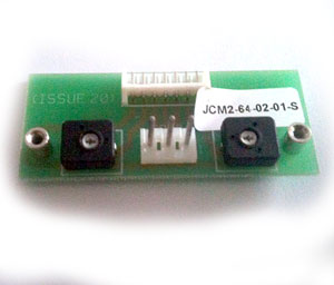
Okay, thank you very much for guiding me through it. Is there any soldering needed to change the bias pots? It looks like it just needs to be unplugged from the connector and then screwed out.
Thanks again.
 

ampmadscientist

Well-Known Member
Joined
Jun 26, 2014
Messages
17,849
Reaction score
12,230
Location
Bio-Isolation Lock Down
Okay, so that's more relieving to hear.

The tubes are fairly new. I had some problems with drifting bias and some overheating(once or twice) when I first bought the amp back in April this year. I changed the tubes back in June with JJ's to see where the problem lied. The bias remained fairly stable after getting the JJ's, though it did fluctuate a little bit over the course of an hour or two (I would check the bias every time I played it, once after 10 minutes of playing, again after about 45-50 mins of playing).

I played the amp with these new tubes probably less than a dozen times before I then changed the circuit board (cause the bias started drifting more). This takes us to now, where I would continue to blow fuses when I would turn the amp on.

If the output tubes are removed, does it still blow a fuse?
 

0caria

Member
Joined
Oct 1, 2018
Messages
44
Reaction score
0
If the output tubes are removed, does it still blow a fuse?
No, only with the power tubes in. It's important I clarify that the fuses started blowing as soon as I replaced the board, literally after putting the new board in I turn it on and the fuse blows. Before I changed the board, I wasn't blowing fuses.
 

ampmadscientist

Well-Known Member
Joined
Jun 26, 2014
Messages
17,849
Reaction score
12,230
Location
Bio-Isolation Lock Down
No, only with the power tubes in. It's important I clarify that the fuses started blowing as soon as I replaced the board, literally after putting the new board in I turn it on and the fuse blows. Before I changed the board, I wasn't blowing fuses.

When the board was tested, did you hook up a speaker to the amp?
Or did you run it without a speaker?

Do any of the output tubes look black / burned or have a white foggy appearance on the inside?
Look at the silver inside the glass.
Is any of them discolored, so that the silver inside the glass looks dark / black / powder white ?

Or do all of them look silver inside - shines like a mirror?

Are any of the output tubes broken at the base?
 

0caria

Member
Joined
Oct 1, 2018
Messages
44
Reaction score
0
When the board was tested, did you hook up a speaker to the amp?
Or did you run it without a speaker?

Do any of the output tubes look black / burned or have a white foggy appearance on the inside?
Look at the silver inside the glass.
Is any of them discolored, so that the silver inside the glass looks dark / black / powder white ?

Or do all of them look silver inside - shines like a mirror?

Are any of the output tubes broken at the base?
Yep, I had the amp connected to the speaker whenever I had the amp operating or warmup(16 ohm cab, out of 16 ohm output). As for the tubes, none of them look foggy or covered in soot or anything. Two or three of them have the slightest hint of black around the middle of the glass, but it's incredibly minimal (looks like a tiny and very faint black smudge, barely noticeable), but it may suggest something's wrong, idk. None of the internals look damaged, burnt or covered in white powder, they're all pretty shiny.
 

ampmadscientist

Well-Known Member
Joined
Jun 26, 2014
Messages
17,849
Reaction score
12,230
Location
Bio-Isolation Lock Down
Yep, I had the amp connected to the speaker whenever I had the amp operating or warmup(16 ohm cab, out of 16 ohm output). As for the tubes, none of them look foggy or covered in soot or anything. Two or three of them have the slightest hint of black around the middle of the glass, but it's incredibly minimal (looks like a tiny and very faint black smudge, barely noticeable), but it may suggest something's wrong, idk. None of the internals look damaged, burnt or covered in white powder, they're all pretty shiny.

Bad bias pot will cause excessive current draw.
I think you should start there and get the bias steady.
 
Top